Distribution multiple freedom robot controlling system
A control system and degree of freedom technology, applied in the direction of program control manipulators, manipulators, manufacturing tools, etc., can solve the problems that local control is difficult to meet the requirements, limit the remote control of robots, and limit real-time planning, and achieve simple structure, low cost, The effect of short development cycle
- Summary
- Abstract
- Description
- Claims
- Application Information
AI Technical Summary
Problems solved by technology
Method used
Image

Examples
Embodiment 1
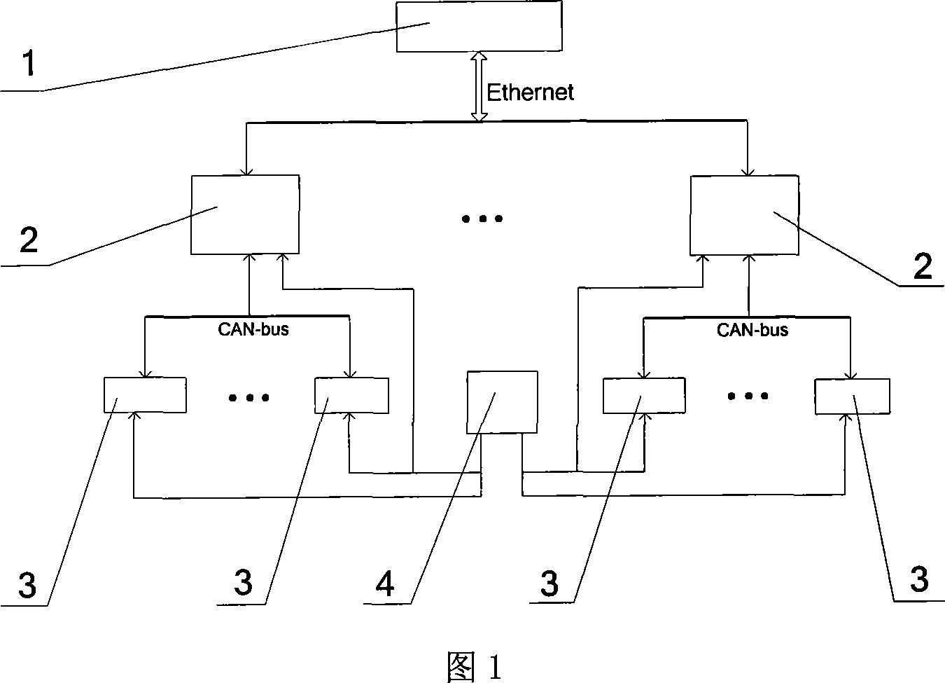
[0029] Embodiment 1 is a wired control system of a distributed multi-degree-of-freedom robot.
[0030]The system is shown in Figure 1 and Figure 5. The industrial computer 1 is directly connected to a "a multi-degree-of-freedom robot motion planning controller" 2 through a twisted-pair cable. The controller" 2 is respectively connected to a plurality of "a DSP-based modular robot independent joint controller" 3 through CAN-bus. The DC power supply 4 is respectively connected with "a multi-degree-of-freedom robot motion planning controller" 2 and multiple "a DSP-based modular robot independent joint controller" 3 .
[0031] The patented technology of "a multi-degree-of-freedom robot motion planning controller" 2 is shown in Figure 5, including a power conversion module 6, a DSP chip 7, an Ethernet controller 8, an Ethernet connector 9, and a CAN bus connection Device 10, CAN bus interface chip 11; the output end of power conversion module 6 is connected with DSP chip 7, Ethern...
Embodiment 2
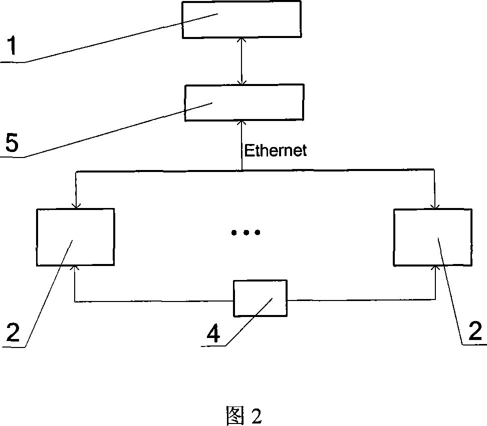
[0036] Embodiment 2 is a wired control system of a distributed multi-degree-of-freedom robot.
[0037] This system is shown in Fig. 1, Fig. 2, Fig. 4, industrial computer 1 is connected with a plurality of "one kind of multi-degree-of-freedom robot motion planning controllers" 2 through router 5 in a wired connection mode, and a plurality of "one kind of multi-freedom robot motion planning controllers" 2 are connected. The robot motion planning controller” 2 is respectively connected to multiple “a DSP-based modular robot independent joint controller” 3 through CAN-bus. The DC power supply 4 is respectively connected to a plurality of "a multi-degree-of-freedom robot motion planning controller" 2 and a plurality of "a DSP-based modular robot independent joint controller" 3 .
[0038] The connection mode between "a multi-degree-of-freedom robot motion planning controller" 2 and "a DSP-based modular robot independent joint controller" 3 is the same as that in Embodiment 1.
Embodiment 3
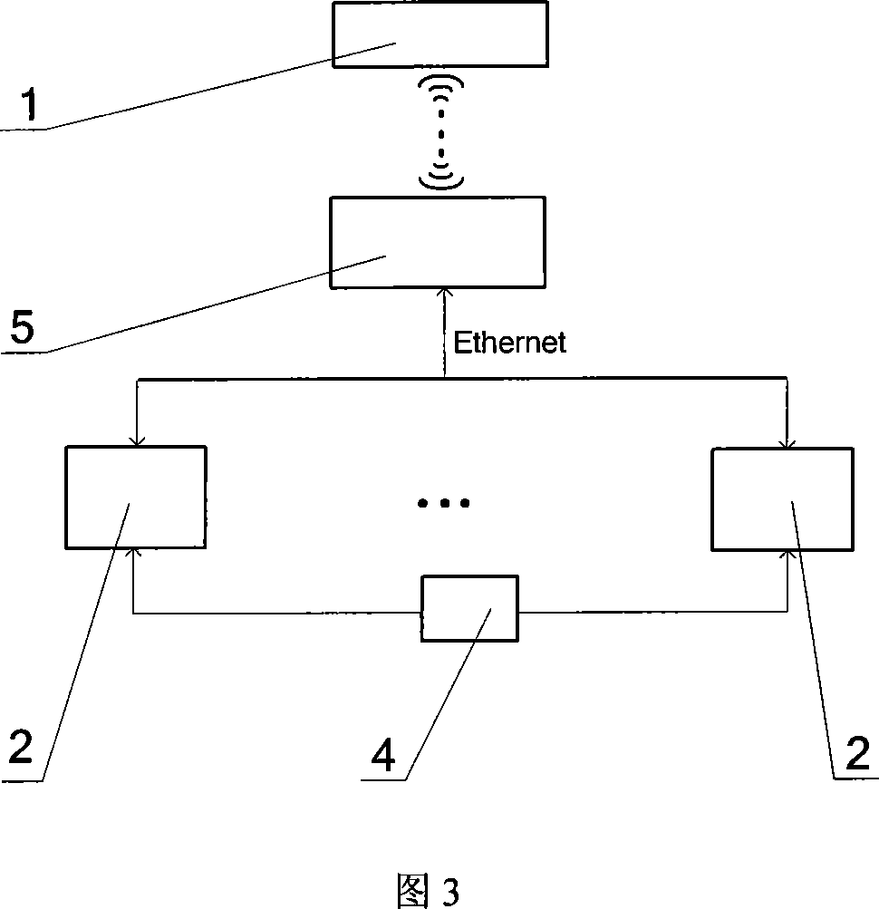
[0039] Embodiment 3 is a wireless control system for a distributed multi-degree-of-freedom robot.
[0040] The system is shown in Fig. 1, Fig. 3 and Fig. 4. The industrial computer 1 is connected to one or more "a multi-degree-of-freedom robot motion planning controller" 2 through a wireless router 5, and one or more "A multi-degree-of-freedom robot motion planning controller" 2 is respectively connected to a plurality of "a DSP-based modular robot independent joint controller" 3 through CAN-bus. The DC power supply 4 is respectively connected with one or more "a multi-degree-of-freedom robot motion planning controller" 2 and a plurality of "a DSP-based modular robot independent joint controller" 3 .
[0041] The connection mode between "a multi-degree-of-freedom robot motion planning controller" 2 and "a DSP-based modular robot independent joint controller" 3 is the same as that in Embodiment 1.
[0042] This embodiment adopts a combined structure, centering on system design...
PUM
 Abstract
Description
Claims
Application Information
 - R&D
- Intellectual Property
- Life Sciences
- Materials
- Tech Scout
- Unparalleled Data Quality
- Higher Quality Content
- 60% Fewer Hallucinations
Browse by: Latest US Patents, China's latest patents, Technical Efficacy Thesaurus, Application Domain, Technology Topic, Popular Technical Reports.
© 2025 PatSnap. All rights reserved.Legal|Privacy policy|Modern Slavery Act Transparency Statement|Sitemap|About US| Contact US: help@patsnap.com