Detection device for panel display test and its production method

A flat-panel display and detection device technology, applied in measuring devices, clothing, applications, etc., can solve problems such as short circuit, decreased accuracy, and poor electromechanical characteristics, and achieve the effects of eliminating noise, reducing failure rate, and suppressing misoperation

Inactive Publication Date: 2007-10-10
CONEM
View PDF0 Cites 3 Cited by
  • Summary
  • Abstract
  • Description
  • Claims
  • Application Information

AI Technical Summary

Problems solved by technology

However, there are problems in that the electromechanical characteristics are poor, the accuracy is reduced due to the generation of noise, and the probes that should be spaced contact each other to cause a short circuit.

Method used


Image

  • Detection device for panel display test and its production method
  • Detection device for panel display test and its production method
  • Detection device for panel display test and its production method

Examples


Embodiment Construction

[0036] Next, preferred embodiments of the present invention will be described with reference to the accompanying drawings. However, the embodiments of the present invention can be changed in various other forms, and it should not be construed that the scope of the present invention is limited only to the embodiments described below.

[0037]1 to 8 are perspective views illustrating a flat panel display testing device and a manufacturing method thereof according to an embodiment of the present invention.

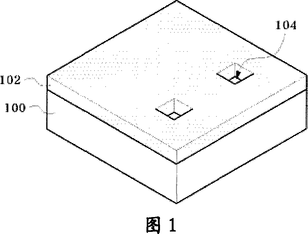
[0038] First, as shown in FIG. 1 , a first mask pattern 102 is formed on a substrate 100 . The substrate 100 may be a silicon substrate. The first mask pattern 102 can be formed by exposure and development steps by photolithography. The first mask pattern 102 has an opening 104 through which a part of the surface of the substrate 100 , that is, the surface of the portion for forming the trench is exposed. Next, etching is performed using the first mask pattern 102 as an et...


PUM


Abstract

The present invention provides an inspection apparatus of testing a flat panel display having a substrate, main body arranged on the substrate, a plurality of probes projecting on two sides of the main body, and probe chip arranged on lower end of the probe projecting on a side of the main body in the probes.

Description

technical field [0001] The present invention relates to an inspection device and a manufacturing method thereof, in particular to an inspection device for testing a flat panel display and a method of fabricating the same (Inspection apparatus of testing a flat panel display and method of fabricating the same). Background technique [0002] Generally, a liquid crystal display (LCD; Liquid Crystal Display), a plasma display (PDP; Plasma Display Panel), and a field emission display (FED; Field Emission Display) are called flat panel displays (FPD; Flat Panel Display). The above-mentioned flat panel display has a pad electrode for applying an electrical signal, and the test of the flat panel display is accomplished by applying an electrical signal to the above-mentioned pad electrode to determine whether it is defective or not. [0003] There are the following types of probes for flat panel display testing, namely: needle type probes made only by manual work; blade type probes m...

Claims


Application Information

Patent Timeline
Patent Type & Authority Applications(China)
IPC IPC(8): G01R31/00G01R1/073
CPCA41D13/04A41D2300/33A41D2400/52A41D2500/50
Inventor 孙埻赫
Owner CONEM
Why Eureka
Try Eureka