Wireless battery status management for medical devices

A medical and wireless technology, applied in the field of wirelessly controlled drug delivery equipment, can solve problems such as insufficient battery power and failure, and achieve good battery management, increased safety, and good reliability.

Inactive Publication Date: 2007-10-10
KONINKLIJKE PHILIPS ELECTRONICS NV
View PDF0 Cites 17 Cited by
  • Summary
  • Abstract
  • Description
  • Claims
  • Application Information

AI Technical Summary

Problems solved by technology

In extreme cases, if one of these devices fails due to insufficient battery power, the results could be disastrous

Method used


Image

  • Wireless battery status management for medical devices
  • Wireless battery status management for medical devices
  • Wireless battery status management for medical devices

Examples


Embodiment Construction

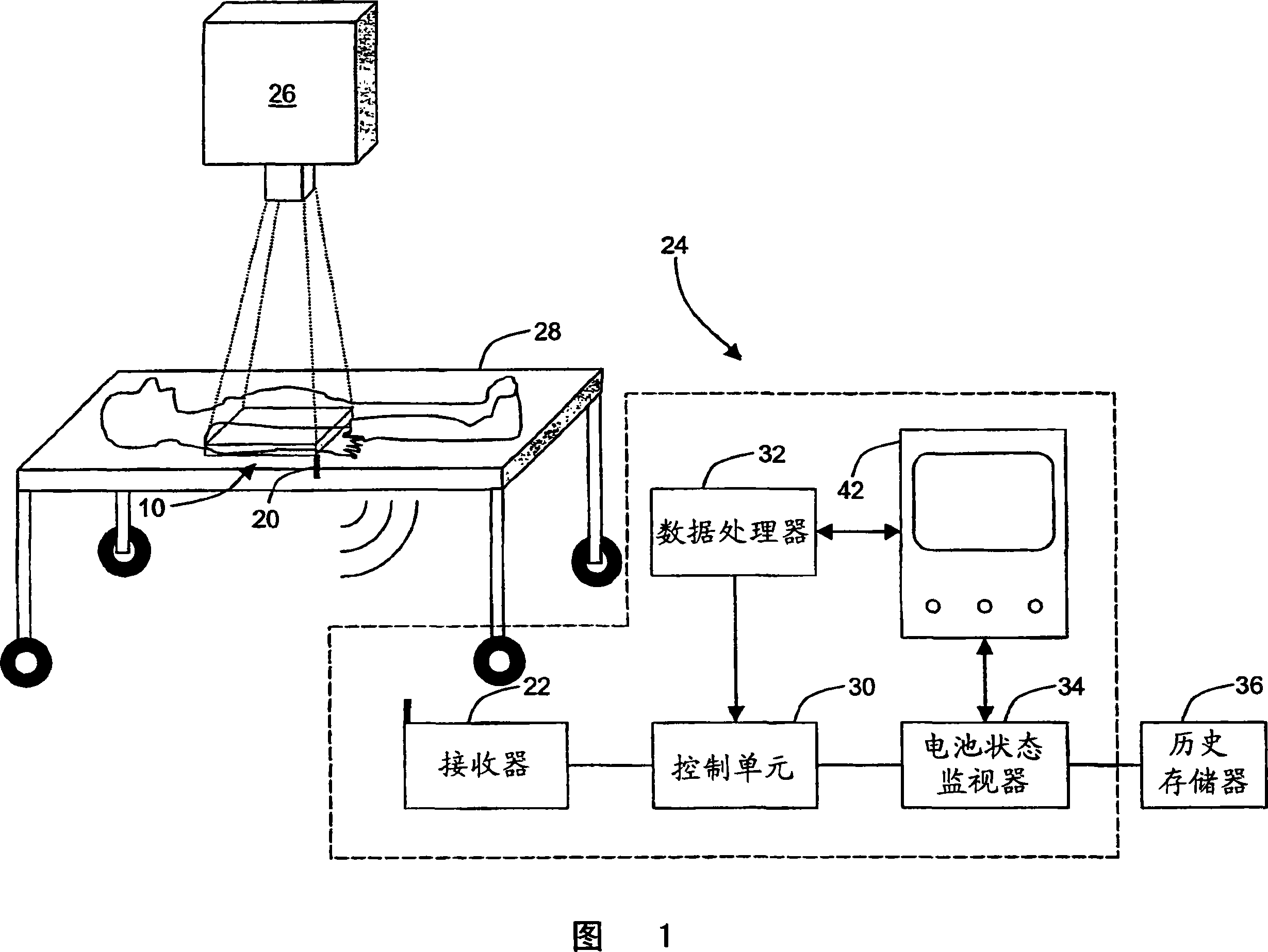
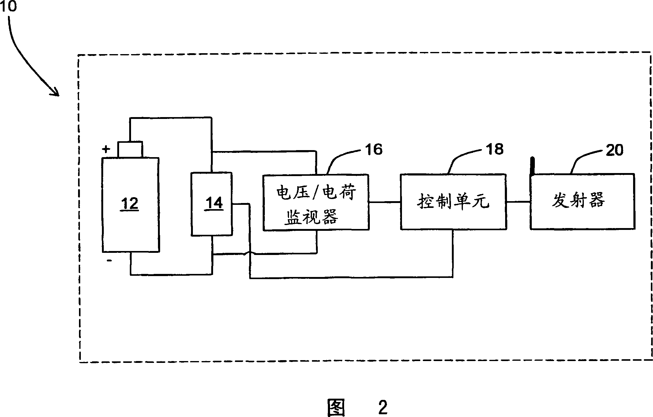
[0022] Referring to Figure 1, a wireless medical component 10 is used in a clinical manner. Because the unit 10 is wireless, the unit 10 has the advantage of being mobile and not fixed to a certain room or location. Since the unit 10 still uses power to perform its functions or communicate, it has a battery or other portable power source. Referring to Figure 2, component 10 is shown in greater detail. The unit 10 is powered by a rechargeable power source or battery 12 . Preferably, the battery 12 is rechargeable so that a user can plug the unit 10 into a docking station to recharge it when not in use. It should be understood that conventional non-rechargeable batteries are also contemplated, although they are somewhat inconvenient. The battery 12 provides power to a functional component 14 such as an electrocardiogram sensor, pulse sensor, blood oxygen sensor, blood measurement sensor, brain wave sensor, temperature sensor, perfusion pump, IV drip controller, patient identi...


PUM


Abstract

In a wireless medical component (10), when it is desired to lessen the clutter of cables and increase mobility and versatility relative to cabled components, a battery life monitor, particularly a voltage monitor (16) takes voltage readings of a battery (12) to assess charge level as the battery (12) drains. The monitored charge level and medical data are transmitted (20) to a receiver (22) associated with a remote host unit (24). The host unit includes historical and typical battery level information and estimates remaining life of the battery (12). Battery life and medical information are displayed on a user interface (42). Typical medical components include ekg sensors, pulse sensors, blood oxygen sensors, blood measure sensors, brain wave sensors, temperature sensors, perfusion pumps, IV drip controllers, patient identification tags or wrist bands, pacemakers, respirators, x-ray detectors, and an MRI coils.

Description

technical field [0001] The present invention relates to wireless patient devices. The wireless patient device has particular application with physiological monitoring devices connected to the patient and communicating wirelessly with each other and with a central unit. However, the invention is also applicable to wirelessly controlled drug delivery devices, such as perfusion pumps, and the like. Background technique [0002] Traditionally, each patient monitor, such as an ECG sensor, pulse sensor, blood oxygen sensor, etc., is connected to its control unit by a cable. This criss-crossing of cables is inconvenient to install and uncomfortable for the patient. Also, moving the patient often requires disconnecting the cables and reconnecting them after the move. In addition to being inconvenient, the patient is also unsupervised during the movement. [0003] In an effort to eliminate cables, battery-operated wireless sensor devices have been proposed. However, when monitor...

Claims


Application Information

Patent Timeline
Patent Type & Authority Applications(China)
IPC IPC(8): G01R31/36A61N1/37
CPCA61N1/3708G01R31/3648G01R31/3693G01R31/3647
Inventor H·-I·马克
Owner KONINKLIJKE PHILIPS ELECTRONICS NV
Why Eureka
Try Eureka