System and method for producing cement short flow-process with metallurgical furnace slag

A technology of metallurgical slag and production system, which is applied in the field of short-process cement production system from metallurgical slag, can solve the problems of long process and uncompleted "zero" discharge of steel slag, and achieve the goal of improving recovery rate, benefiting environmental protection and shortening the process flow Effect

Active Publication Date: 2007-10-17
张维田 +1
View PDF7 Cites 13 Cited by
  • Summary
  • Abstract
  • Description
  • Claims
  • Application Information

AI Technical Summary

Problems solved by technology

The method of this patent belongs to the off-line processing method, the process of this method is long, and only steel slag is processed into granulated slag, and th...

Method used


Image

  • System and method for producing cement short flow-process with metallurgical furnace slag
  • System and method for producing cement short flow-process with metallurgical furnace slag
  • System and method for producing cement short flow-process with metallurgical furnace slag

Examples


Embodiment 1

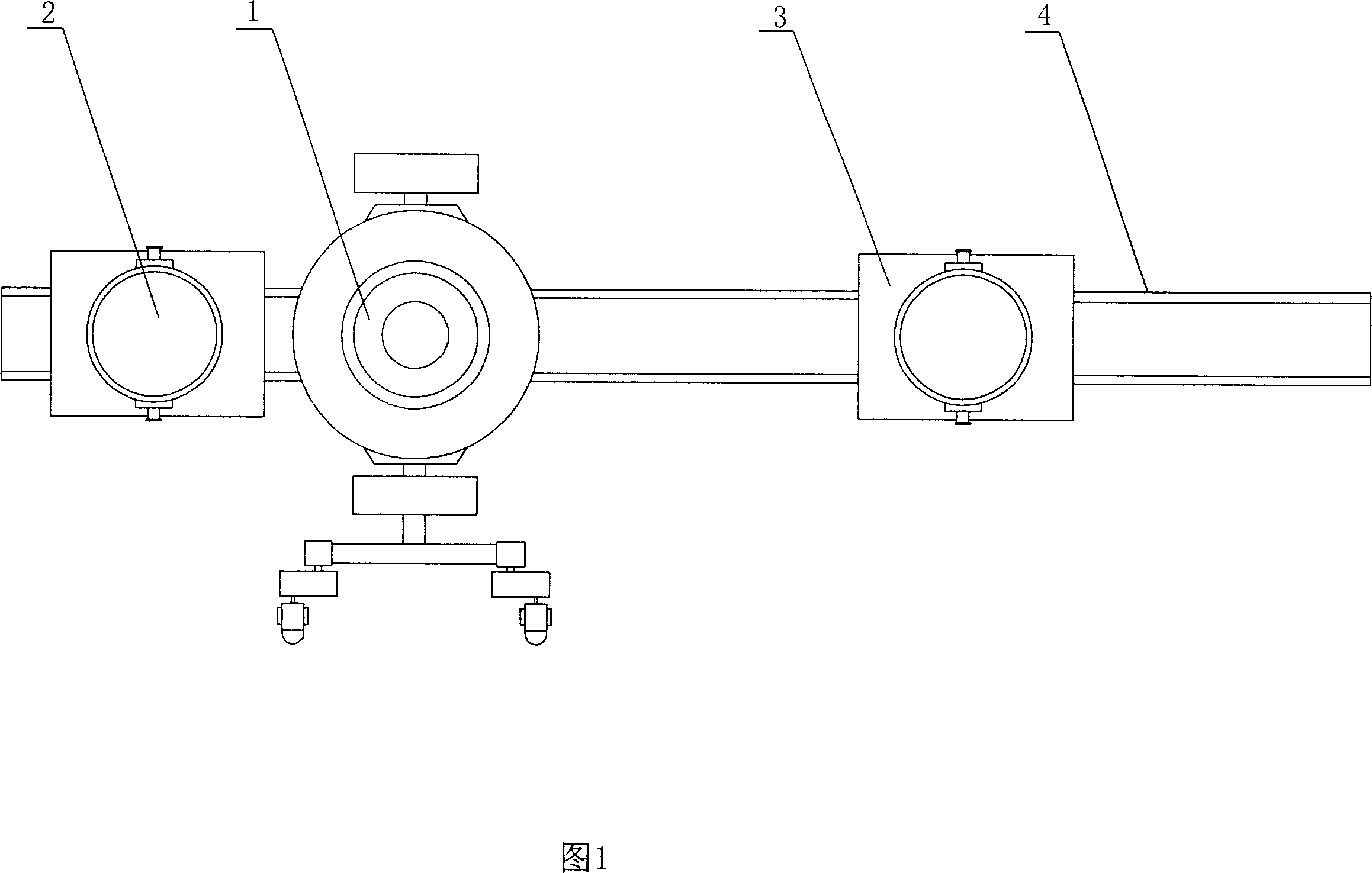
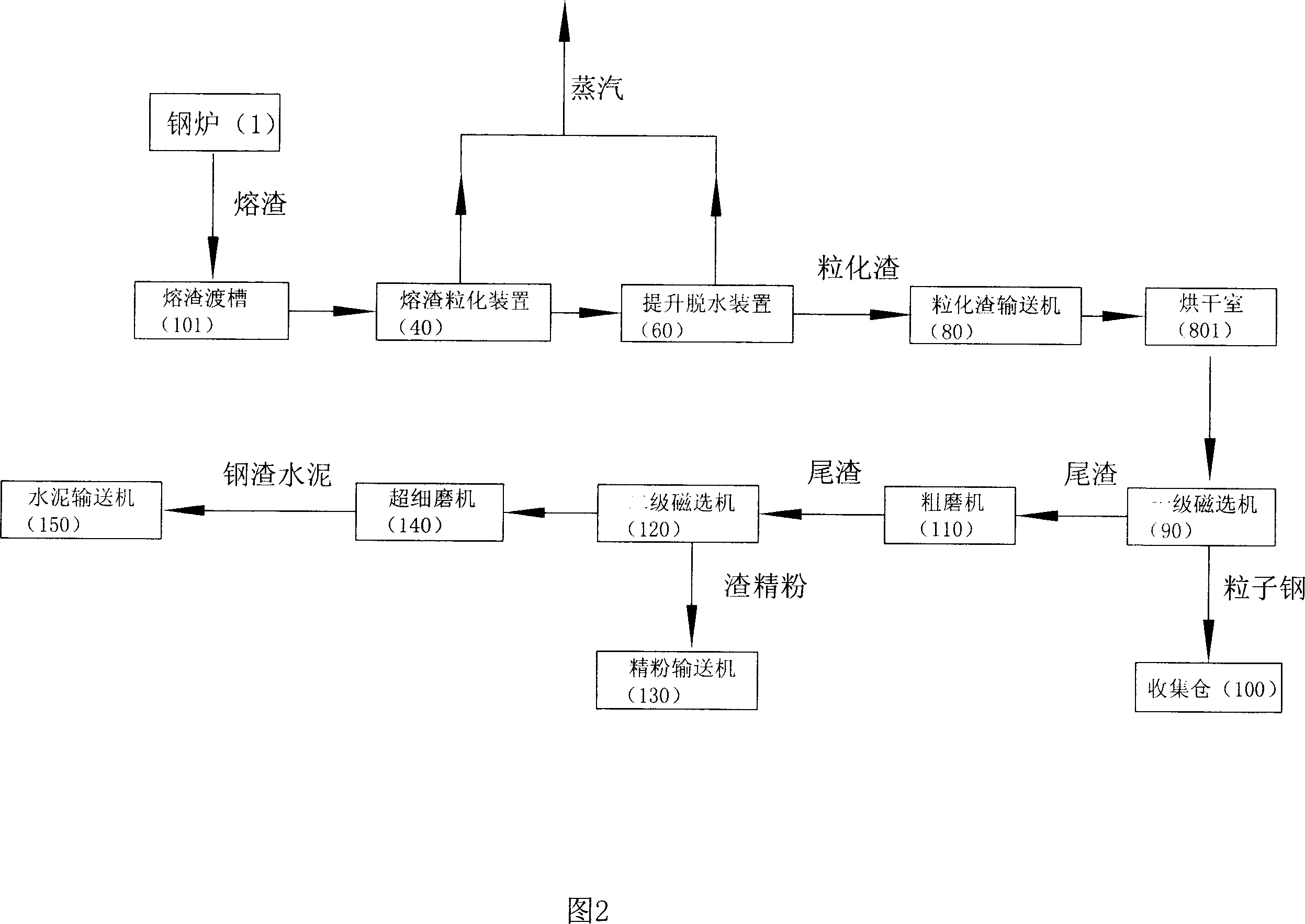
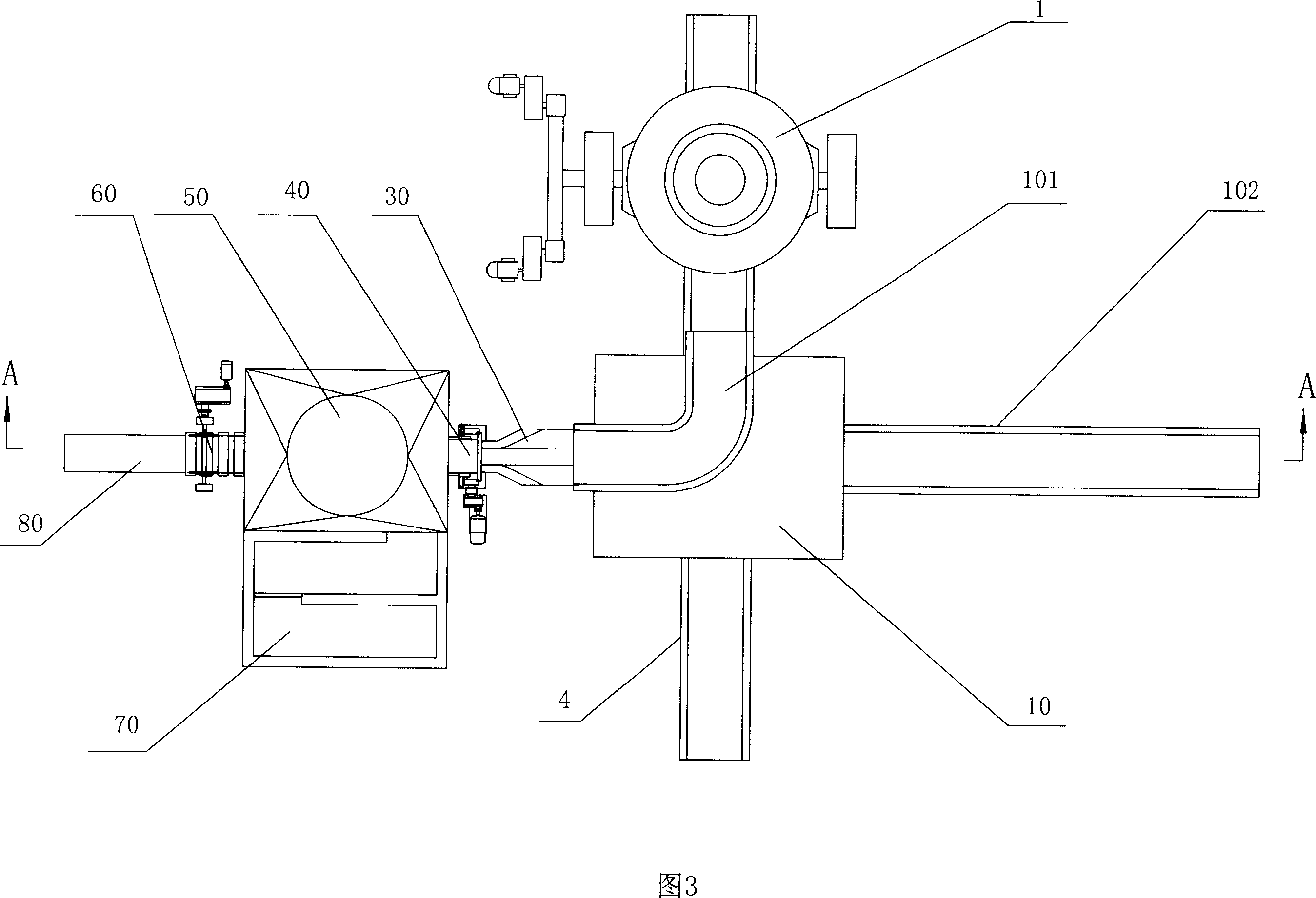
[0035]Referring to Fig. 2, Fig. 3 and Fig. 4, a metallurgical slag cement short-process production system includes a steel furnace 1 (the steel furnace can be a converter or a non-ferrous metal smelting furnace), a slag tank car walking track 4 in front of the furnace, and a slag tank car A slag granulation device 40 is arranged on one side of the walking track, and a slag aqueduct car walking track 102 is arranged on the other side of the slag tank car walking track. 10, a diverted slag aqueduct 101 is installed. In this embodiment, a slag granulation device is arranged on the left side, and a slag aqueduct vehicle is arranged on the right side. The diverted slag aqueduct is a 90° diverted aqueduct, and The running track of the slag aqueduct car and the walking track of the slag tank car are arranged orthogonally. The inlet end of the slag aqueduct can be docked with the slag outlet of the steel furnace 1 (due to the conventional structure, the slag outlet is not shown in the...

Embodiment 2

[0040] Referring to Fig. 5, this embodiment is an improvement on the basis of Embodiment 1. In this embodiment, the diverted slag aqueduct is a 90° diverted aqueduct, and the walking track of the slag aqueduct car and the slag tank car The walking track is set obliquely. That is, the traveling track of the slag aqueduct car and the traveling track of the slag tank car are obliquely arranged at an angle of 30° to 60°. The advantage of oblique setting is to reduce the use area of ​​the equipment.

Embodiment 3

[0042] Referring to Fig. 6 and Fig. 7, this embodiment is an improvement on the basis of the first embodiment. In the production system of this embodiment, it includes a steel furnace 1 and a slag tank car running track 4 in front of the furnace. A slag granulation device 40 is arranged on one side of the slag tank car running track, and a slag aqueduct car is set on the other side of the slag tank car running track. Track 102, one end of the traveling track of the slag aqueduct vehicle intersects with the traveling track of the slag tank vehicle, and a steering type slag aqueduct 101 is installed on the slag aqueduct vehicle 10. In this embodiment, a slag granulation device is arranged on the left side, and the right side A slag aqueduct car is arranged on the side, and the diverted slag aqueduct is a 90°-turned aqueduct, and the traveling track of the slag aqueduct car and the traveling track of the slag tank car are arranged orthogonally. A slag buffer tank 20 is arranged a...


PUM


Abstract

The present invention relates to a short stage production system for metallurgical slag cement. A slag granulating device is arranged on one side of the traveling rail of slag car, a slag flume car traveling rail is arranged at the other side of the traveling rail of slag car, the slag flume car is provided with a slag flume, the inlet end of the slag flume is connected with the steel furnace slag hole by abutting joint, the outlet end of the slag flume is connected with the chute of the slag granulating device by abutting joint. A collecting basin with a grain slag lift and dewater unit therein is arranged at the granulating outlet of the slag granulating device, the discharge end of the lift and dewater unit is provided with a grain slag conveyor, the discharge end of the grain slag conveyor is arranged above the entrance of a first level magnetic separator, the tailings outlet of the magnetic separator is connected with the inlet end of a kibbling mill by means of a tailings conveyor, the discharge opening of the kibbling mill is connected with the inlet end of a second level magnetic separator, the slag fine powder outlet of the second level magnetic separator is connected with a fine powder conveyor, the tailings outlet of the second level magnetic separator is connected with the inlet end of a superfine mill, the outlet of the superfine mill is connected with a cement conveyor.

Description

technical field [0001] The invention relates to a short-process system and method for producing cement from metallurgical slag. The system and method can perform superfine powder treatment on steel slag or non-ferrous metal slag, and separate metal particles from non-metal particles. The system has a short process, no explosion, safety, and environmental protection. It can realize the real on-line direct processing of metallurgical slag and process it into cement through ultra-fine grinding after magnetic separation or jigging screening, so that the treatment rate of metallurgical slag can reach 100%. Background technique [0002] The metallurgical industry of various countries in the world will discharge about 130kg of steel slag, 300kg of iron-containing powder slag and other waste materials for every ton of crude steel produced. The annual discharge of steel slag in the world is about 100-150 million tons. There are more than 100 million tons of steel slag accumulated in...

Claims


Application Information

Patent Timeline
IPC IPC(8): B28B15/00B28B1/54C04B5/02F26B17/02
CPCC04B5/00C04B18/141C21B3/08C21B3/10C21B2400/024C21B2400/032C21B2400/052C21B2400/056C21B2400/072Y02W30/91C04B20/026
Inventor 张维田霍岭
Owner 张维田
Why Eureka
Try Eureka