Integrated series-parallel combined electrolysis bath

An electrolytic cell and combined technology, applied in the field of electrolytic cells, can solve the problems of low utilization rate of electrode materials, many closed end faces of electrolytic cells, poor working conditions and parameters, etc. Effect

Active Publication Date: 2007-10-17
ZHEJIANG HELI HYDROGEN ENERGY TECH CO LTD
View PDF2 Cites 11 Cited by
  • Summary
  • Abstract
  • Description
  • Claims
  • Application Information

AI Technical Summary

Problems solved by technology

The current electrolytic cell structure is like the "hydrogen oxygen generator" in Chinese patent 96249548.4, which is concentric cylinder type. Since the area of ​​each electrode sheet is different, the inner layer area is the smallest, the working condition parameters are the worst, and the electrode consumption is the fastest, then The inner electrode sheet determines the service life of the overall electrolytic cell, and the utilization rate of electrode materials is low
There is also a Chinese patent 94207129.8 "electrolyte self-circulating hydrogen-oxygen generator". Due to the characteristics and structure of the rubber insulating material, the electrolytic cell has many closed ends, a large area, and complex assembly, resulting in low overall pressure and easy leakage

Method used


Image

  • Integrated series-parallel combined electrolysis bath
  • Integrated series-parallel combined electrolysis bath
  • Integrated series-parallel combined electrolysis bath

Examples


Embodiment 1

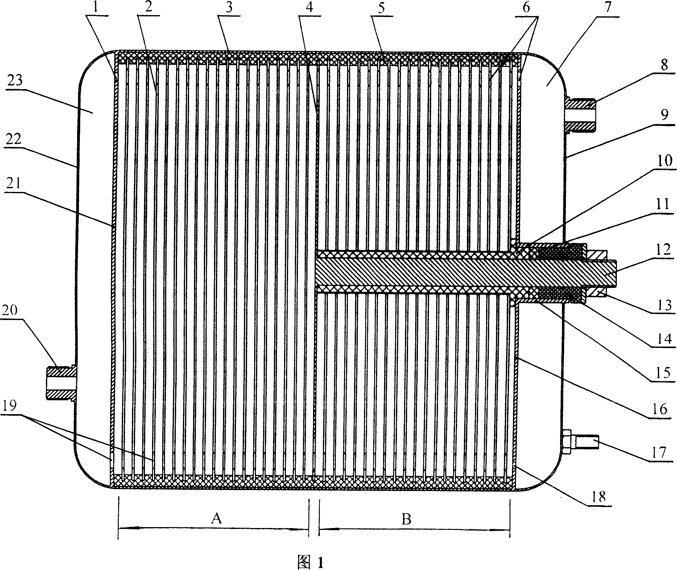
[0022] Embodiment 1 Referring to FIG. 1 , the insulating ring 5 is integral, and its inner ring is provided with equidistant ring grooves, and each ring groove has the same depth and thickness, and is used to embed the electrode sheet 2 . The liquid inlet 20 is welded at the bottom of the left end cover 22 , the gas-liquid outlet 8 is welded at the top of the right end cover 9 , and the cathode screw 17 is welded at the bottom of the right end cover 9 . The upper part of the left end plate 21 is provided with a guide hole 1, and the lower part is provided with a liquid guide hole 19. The upper part of the right end plate 16 is provided with an air guide hole 6, and the lower part is provided with a guide hole 18. The function of the guide holes is to strengthen the flow of liquid and prevent internal Impurities precipitate. A liquid buffer zone 23 and a gas-liquid buffer zone 7 are respectively formed between the end plates on both sides and the end covers on both sides. The ...

Embodiment 2

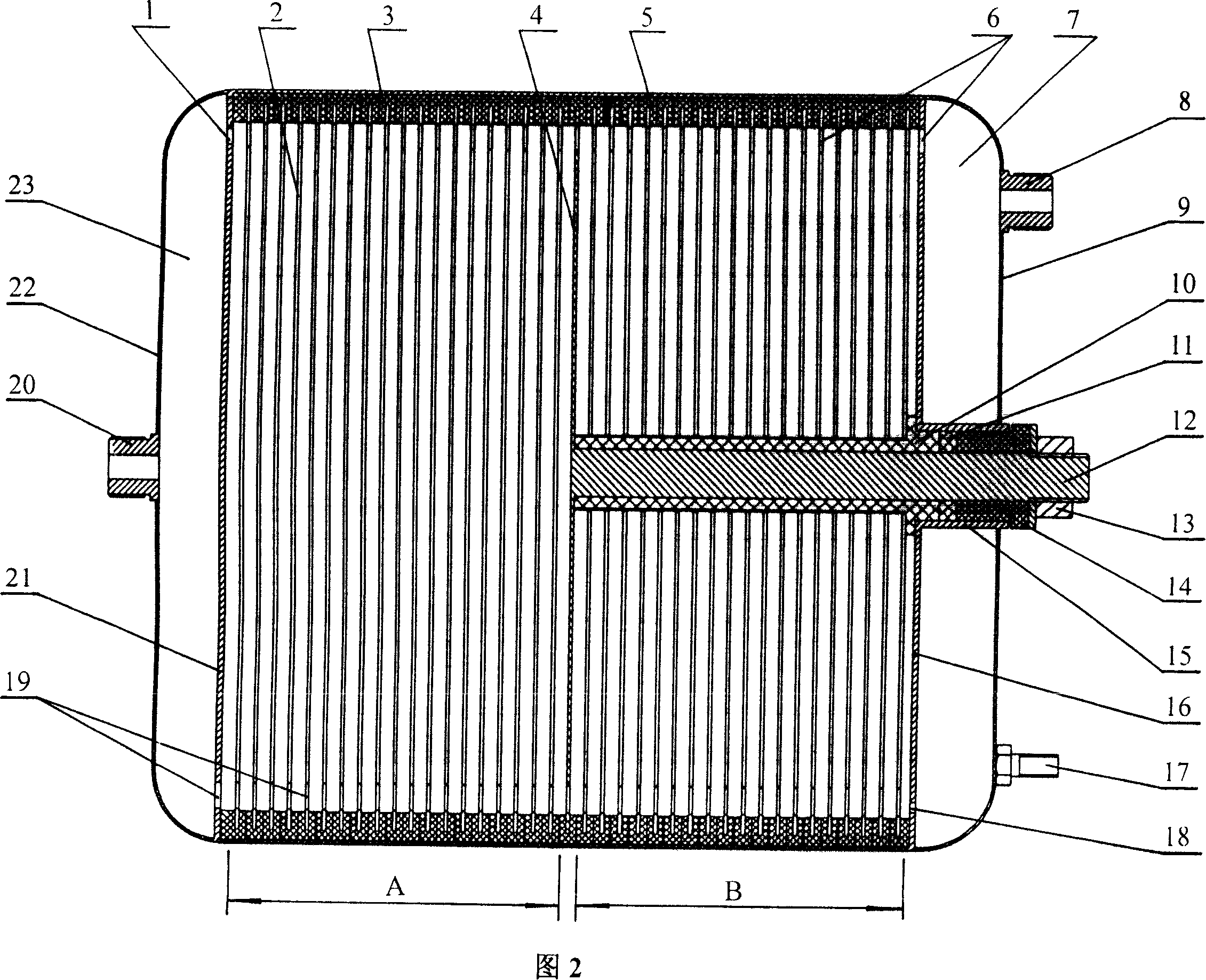
[0023] Embodiment 2 Referring to Fig. 2, the insulating ring 5 is multi-piece stacked, and the inner ring of each insulating ring is provided with equidistant annular grooves of the same specification, and the electrode sheets 2 are embedded. The liquid inlet 20 is welded in the middle of the left end cover 22, the gas-liquid outlet 8 is welded in the upper part of the right end cover 9, and the cathode screw 17 is welded in the lower part of the right end cover 9. The effects of the liquid buffer and the gas-liquid buffer of this scheme are the same as in Example 1.

Embodiment 3

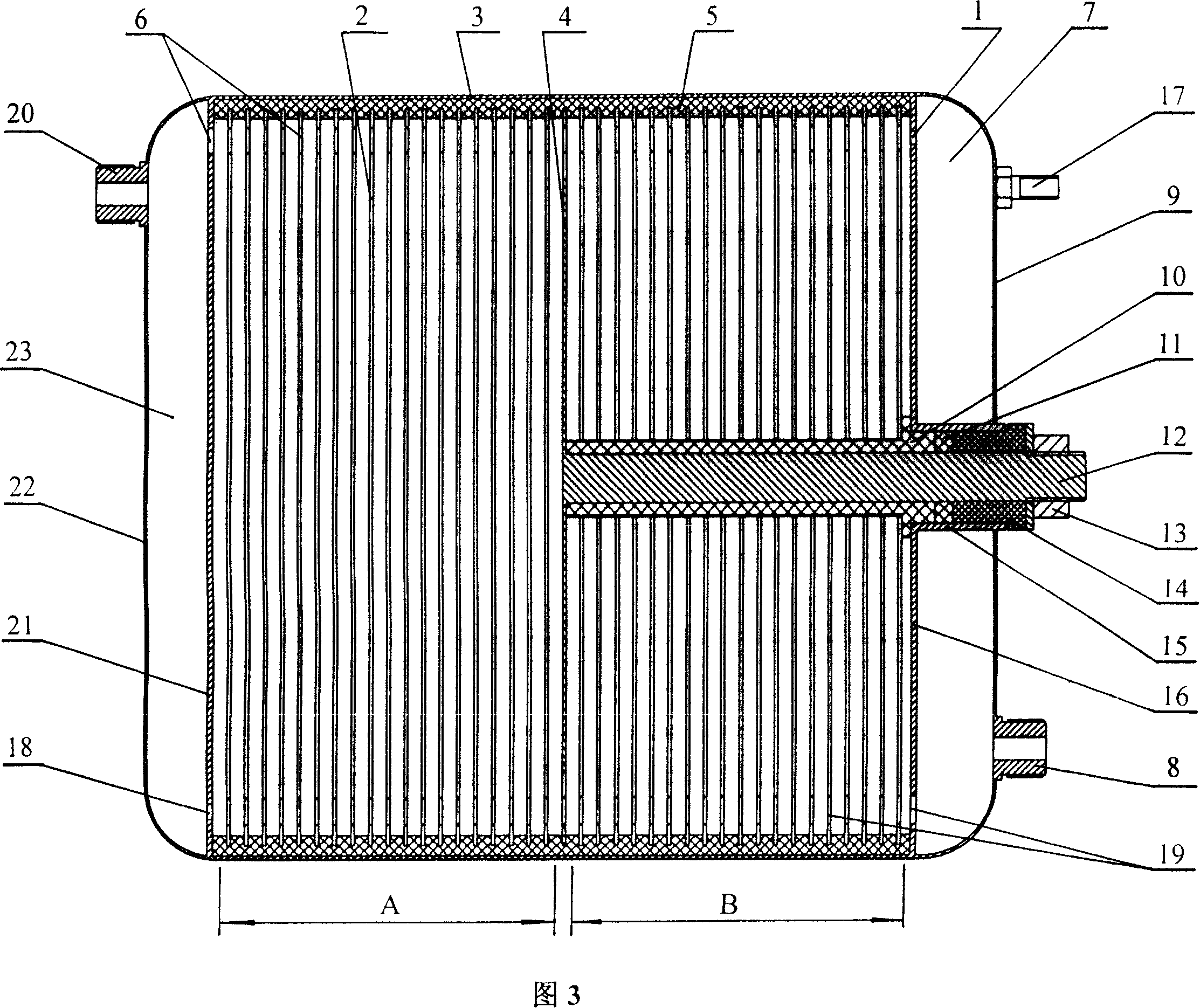
[0024] Referring to Fig. 3 for embodiment 3, the insulating ring 5 is the same as that of embodiment 1. The liquid inlet 20 is welded on the top of the left end cover 22 . The cathode screw 17 is welded on the upper part of the right end cover 9, and the gas-liquid outlet 8 is welded on the lower part of the right end cover 9. The liquid buffer of this scheme serves as a buffer for the liquid flowing out from the air guide hole and the guide hole, and the gas-liquid buffer serves as a buffer for the liquid flowing out of the guide hole and the liquid guide hole.


PUM


Abstract

The present invention discloses an integration serial-parallel combination type electrolytic tank. Inside a closing barrel, there are provided electrode plates with identical plate number and contour dimension, which are serial-parallel combinated with identical space length to A zone and B zone or opposite direction setup double- serial-parallel combinated to B zone, A zone, A zone and B zone, wherein the electrode plates are isolated from the closing barrel inner walls by an insulation ring, the anodic leadout bar for connecting the anodic electrode plates is leaded-out of the closing barrel through an insulated isolation tube, conduit tubes and the like and is then locked, the closing barrel is equiopped wth liquid intake, gas-liquid out spout and cathode screw rod, the end sheets at both ends and the electrode plates are equipped with guide holes, liquid guide holes, gas guide holes and leading holes thereon. Since a reasonable combination type inner serial-parallel electrolytic tank structural is adopted and hermeticity, bearing, insulativity and electrode material utilization of the electrolytic tank are taken thoroughly into accound, a system with compact complete texture, high bearing, fine sealing without leakage, identical electrode plates service life, simple and reliable electric(al) service connection can be constituted according to what one needs to efficaciously resolve large-sizing problems of a hydrogen and oxygen making equipment, with reduced floor area.

Description

technical field [0001] The invention relates to an electrolytic cell capable of electrolyzing electrolyte solution to generate hydrogen-oxygen mixed gas, in particular to an integrated series-parallel combined electrolytic cell. Background technique [0002] The hydrogen-oxygen mixed gas generated by the electrolyte is used as a gas source, which can be used for metal heating, welding, cutting, catalytic combustion of substances, catalytic reactions, etc. The current electrolytic cell structure is like the "hydrogen oxygen generator" in Chinese patent 96249548.4, which is concentric cylinder type. Since the area of ​​each electrode sheet is different, the inner layer area is the smallest, the working condition parameters are the worst, and the electrode consumption is the fastest, then The inner electrode sheet determines the service life of the overall electrolytic cell, and the utilization rate of electrode materials is low. There is also a Chinese patent 94207129.8 "elec...

Claims


Application Information

Patent Timeline
IPC IPC(8): C25B1/06C25B9/06C25B9/17
CPCY02E60/366Y02E60/36
Inventor 梁宝明李生平常学斌
Owner ZHEJIANG HELI HYDROGEN ENERGY TECH CO LTD
Why Eureka
Try Eureka