Horizontal radiation type electrolysis method and device

A technology of electrolysis device and electrolysis method, which is applied in electrolysis process, electrolysis components, chemical instruments and methods, etc., can solve the problems of breeding bacteria, inability to adjust, and increase cost, so as to reduce the generation of turbulent flow, facilitate diversion, and stabilize water flow. Effect

Active Publication Date: 2007-10-17
徐文星
View PDF0 Cites 12 Cited by
  • Summary
  • Abstract
  • Description
  • Claims
  • Application Information

AI Technical Summary

Problems solved by technology

[0003] 1. Most of the acid and alkaline water outlets of the vertical electrolytic cell are designed to take water from the top, resulting in residual water retention in the electrolytic cell after electrolysis. Additional residual water discharge devices need to be installed, which increases costs. If there is no residual water discharge device , the residual water will breed bacteria, and also cause calcium ions to precipitate, which will accelerate calcium accumulation in the electrolytic tank. When electrolyzing again, the previous residual water will flow out without complete electrolysis, and cannot reach the standard value of oxidation-reduction potential
[0004] 2. The unit area of ​​the water inlet and the water outlet of the vertical electrolyzer is equal, and the electrolysis current is also similar. If you want to increase the electrode spacing of the water outlet, the resistance of the water outlet will be relatively increased, and the total electrolysis current at the water outlet will be reduced. , relatively reducing the scope of the neutral water layer, relatively making the separation of anions and cations more difficult
[0005] 3. The unit area of ​​the water inlet and the water outlet of the vertical electrolyzer is equal, and the flow velocity entering the electrode plate inlet is equal to the flow velocity leaving the electrode plate outlet, which cannot slow down the flow velocity of the water outlet, and it is relatively easy to generate turbulent flow.
[0006] 4. The vertical electrolyzer is generally designed with the water inlet at the bottom and the water outlet a

Method used


Image

  • Horizontal radiation type electrolysis method and device
  • Horizontal radiation type electrolysis method and device
  • Horizontal radiation type electrolysis method and device

Examples


Embodiment 1

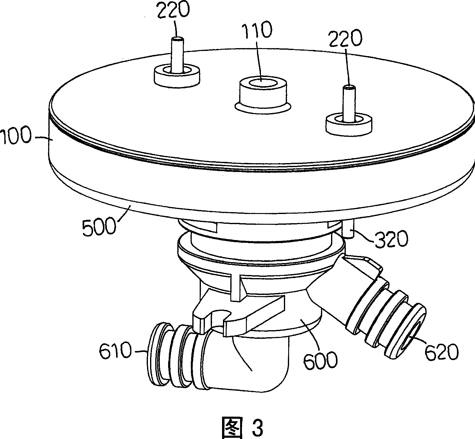
[0189] Embodiment 1, please refer to FIG. 3 and FIG. 4 , which are three-dimensional assembly and three-dimensional disassembly diagrams of Embodiment 1 of the present invention. And as shown in FIG. 5 , which is a cross-sectional schematic diagram of Embodiment 1 of the present invention. The electrolysis device is mainly composed of a cover body 100, an anode electrode plate 200, a cathode electrode plate 300, a diverter plate 400, a seat body 500, a water joint 600, and a plurality of water-stop gaskets Q10, Q20, and Q30; wherein:

[0190] The cover 100 is disc-shaped, the center of the cover 100 is provided with a water inlet 110, the inner surface of the cover 100 can accommodate the anode electrode plate 200, and the outer surface of the cover 100 is provided with two through holes 120 for the anode The two positive conductive parts 220 of the electrode plate 200 pass through, and the inner wall of the cover 100 is provided with an internal thread 130 for locking the sea...

Embodiment 2

[0197] Embodiment 2, the horizontal radiant electrolysis device provided by the present invention, in addition to being able to be designed as embodiment 1 enters water from one side of the cover body 100, and then discharges water from the two sides below the water joint 600, it can also be designed to flow from the water The water enters from the lower part of the joint 600, and then the water comes out from the cover body 100 and the water joint 600 respectively. Please refer to FIG. 8, which is a three-dimensional exploded view of the second embodiment of the present invention. And as shown in FIG. 9 , which is a cross-sectional schematic diagram of Embodiment 2 of the present invention. The electrolysis device is mainly composed of a cover body 100', an anode electrode plate 200', a cathode electrode plate 300', a diverter plate 400', a seat body 500', a water connector 600', an annular diverter device 700' and a plurality of water-stop gaskets. Composed of Q10', Q20', Q3...

Embodiment 3

[0206] Embodiment 3, the horizontal radiant electrolysis device provided by the present invention can be designed to enter water from one side of the cover body 100 in Embodiment 1, and then discharge water from the two sides below the water joint 600, which is similar to Embodiment 2 from the water joint 600 In addition to the form of entering water from the lower side and then exiting water from the cover body 100' and the water joint 600', it can also be designed to enter water from the water joint 50 and then exit the water from the center of the water joint 50 and the other side respectively. For the form, please refer to Fig. 12 and Fig. 13, which are the three-dimensional combination cut-away schematic diagram and the three-dimensional exploded schematic diagram of the third embodiment of the present invention. As shown in FIG. 14 , it is a cross-sectional schematic diagram of Embodiment 3 of the present invention. And as shown in FIG. 15 , which is a partially enlarged...


PUM


Abstract

The present invention relates to a horizontal radial type electrolytic method and apparatus, particularly wherein an electropad is set between the casing and the horizontal corresponding surface of the base and a water intake is provided at the center of the electropad. The raw water flows-in directly from the water intake and flows off outwards in a manner of horizontal radiat pervasion. During electrolysis, an acidic aqueous layer and an alkaline aqueous layer are respectively formed at parallel sides of anode electropad and cathode electropad. Two water exit routes are set at places correspondin to the electropad at the casing and the base, thereby the acidulous water and the alkaline water are discharged in splitted streams. The present invention is capable of depressing electroanalysis cost and resolving effectively problems of remaining water breeding bacilli and remaining water accelerating calcium deposition.

Description

technical field [0001] The invention relates to a horizontal radiation type electrolysis method and device, which is mainly applied to the technology of steady water flow in an electrolyzed water machine. Background technique [0002] The conventional known vertical electrolyzer has the following problems: [0003] 1. Most of the acid and alkaline water outlets of the vertical electrolytic cell are designed to take water from the top, resulting in residual water retention in the electrolytic cell after electrolysis. Additional residual water discharge devices need to be installed, which increases costs. If there is no residual water discharge device , Residual water will breed bacteria and cause calcium ion precipitation, which will accelerate calcium accumulation in the electrolytic cell. When electrolysis is performed again, the previous residual water will flow out without complete electrolysis, which cannot reach the standard value of redox potential. [0004] 2. The un...

Claims


Application Information

Patent Timeline
IPC IPC(8): C25B9/00C25B1/00C02F1/461
Inventor 徐文星
Owner 徐文星
Why Eureka
Try Eureka