Optical angle gauge test calibrator utilizing mutual orthogonal double-frequency laser interferometer

A dual-frequency laser interferometry and calibrating instrument technology, which is applied in the direction of optical devices, instruments, and measuring devices, can solve the problems of large interpretation errors, small measurement ranges, and great influence on the accuracy of measuring the deflection angle of optical angle gauges. Influence, the effect of improving accuracy

Inactive Publication Date: 2007-11-07
BEIJING INSTITUTE OF TECHNOLOGYGY
View PDF0 Cites 10 Cited by
  • Summary
  • Abstract
  • Description
  • Claims
  • Application Information

AI Technical Summary

Problems solved by technology

[0005] Among them, the self-collimation method is a relatively direct method for measuring the deflection angle of the standard optical goniometer. Its disadvantages are: the measurement range is affected by the field angle of the autocollimation telescope, and the measurement range is small; this method requires knowing the refraction of the optical goniometer material At the same time, the measurement accuracy is affected by the accuracy of the autocollimat

Method used


Image

  • Optical angle gauge test calibrator utilizing mutual orthogonal double-frequency laser interferometer
  • Optical angle gauge test calibrator utilizing mutual orthogonal double-frequency laser interferometer

Examples


Embodiment Construction

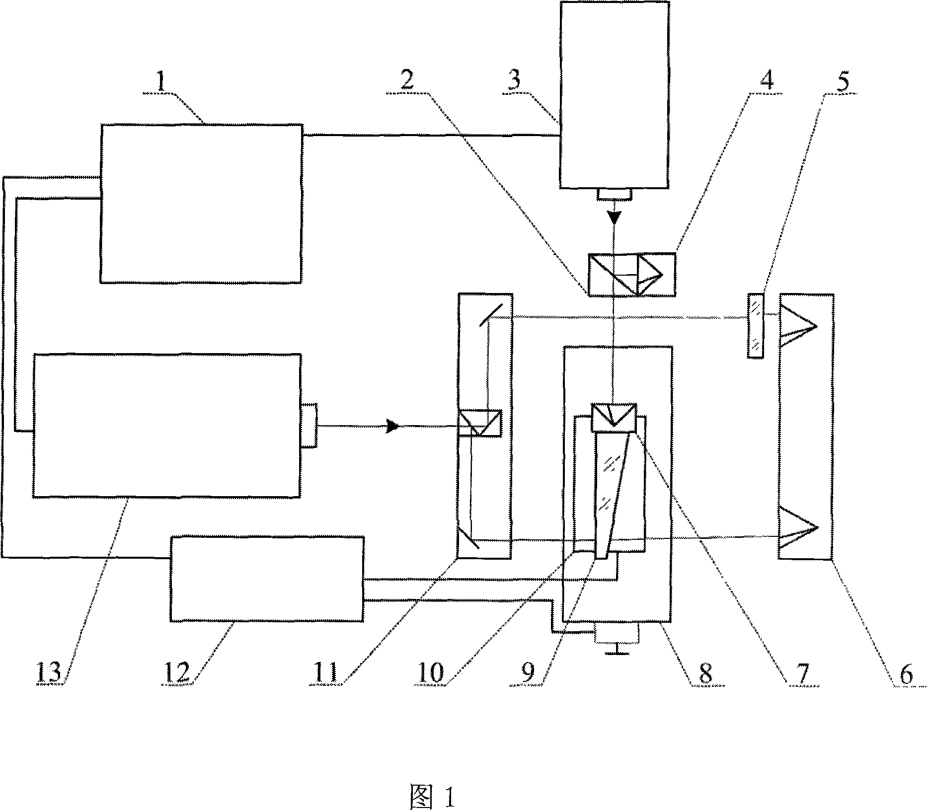
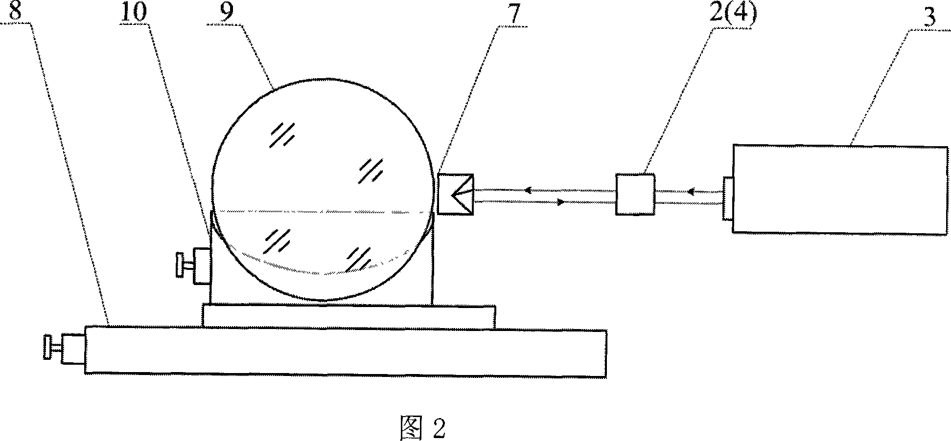
[0019] As shown in Figure 1, the present invention utilizes the optical angle gauge test calibration instrument of mutually orthogonal dual-frequency laser interferometer to comprise two mutually perpendicular optical paths, wherein one optical path is dual-frequency laser interferometer A3, dual-frequency laser interferometer A The beam splitter 2, the dual-frequency laser interferometer A static mirror 4, the dual-frequency laser interferometer A moving mirror 7 and the precision translation stage 8 are used to measure the actual distance that the optical angle gauge moves in a plane parallel to its main section . The other optical route consists of a dual-frequency laser interferometer B13, a long baseline beam splitter 11, an optical path compensation parallel glass plate 5, a long baseline mirror 6 and a precision angular displacement stage 10, which is used to measure the thickness change of the optical angle gauge during the movement process The amount of optical path c...


PUM


Abstract

The invention discloses a high accuracy use mutual orthogonal two double frequencies laser interferometer optics angle gauge testing marking apparatus, which includes controlled computer 1, double frequency laser interferometer A3 and rays direction 2,the static reflector 4 and the motion reflector 7 of placed in turn according to light path direction, double frequency laser interferometer B13 which mutually vertical laying aside with double frequency laser interferometer A3 rays path, the long baseline spectroscope 11, the long baseline reflector 6, the optical path compensate parallel glass plate 5 and the measured photometry angle gauge 9 which in turn placed according to the double frequency laser interferometer B13 light path, and also includes migration precise translation 8, small rotation precise angular displacement 10 and step motor control box 12 of making the measured optic angle gauge 9 along the main section direction move. The invention has the following remarkable merit: through the invention installment survey optics angle gauge angle of deviation in 2'-10'survey scope, the measuring accuracy may achieve 0.02', enormously increased optics angle gauge angle of deviation angular accuracy. Uses the mutual orthogonal double frequency laser interferometer take a bearing, reduced the optical material refractive index and the interference fringe interprets and so on other factors influence to take a bearing precision.

Description

technical field [0001] The invention belongs to the field of small-angle measurement and measurement, and relates to a method and a device for realizing high-precision measurement and calibration of the deflection angle generated by monochromatic light passing through an optical angle gauge. The calibrated optical angle gauge can be used as a standard small-angle generator or a small-angle reference to complete the test and calibration of the indication error of the autocollimator micrometer, theodolite subdivision reading system, and goniometric instruments. Background technique [0002] Small-angle metrology is an important part of metrology science. With the upgrading and industrialization of photoelectric digital image testing instruments, the demand for small-angle measurement is increasing, and the requirements for its accuracy are also getting higher and higher. In the aerospace measurement and control system, a high-precision small-angle generator is required to pro...

Claims


Application Information

Patent Timeline
IPC IPC(8): G01B9/02
Inventor 何川林家明沙定国任建荣邹桂兰张旭升陈凌峰周桃庚
Owner BEIJING INSTITUTE OF TECHNOLOGYGY
Why Eureka
Try Eureka