Hydraulic speed buffer control system and control method

A hydraulic retarder and control system technology, applied in the direction of liquid shock absorbers, etc., can solve the problems of inaccurate control accuracy, difficult manufacturing, high processing accuracy, etc., and achieve good processing technology, high accuracy, and stable quality Effect

Active Publication Date: 2007-11-14
深圳市大为创新科技股份有限公司
View PDF0 Cites 22 Cited by
  • Summary
  • Abstract
  • Description
  • Claims
  • Application Information

AI Technical Summary

Problems solved by technology

At present, hydraulic retarders generally use a control system composed of oil pumps, complex control valves, complex oil passages, controllers, etc., which is relatively difficult to manuf

Method used


Image

  • Hydraulic speed buffer control system and control method
  • Hydraulic speed buffer control system and control method
  • Hydraulic speed buffer control system and control method

Examples


Embodiment Construction

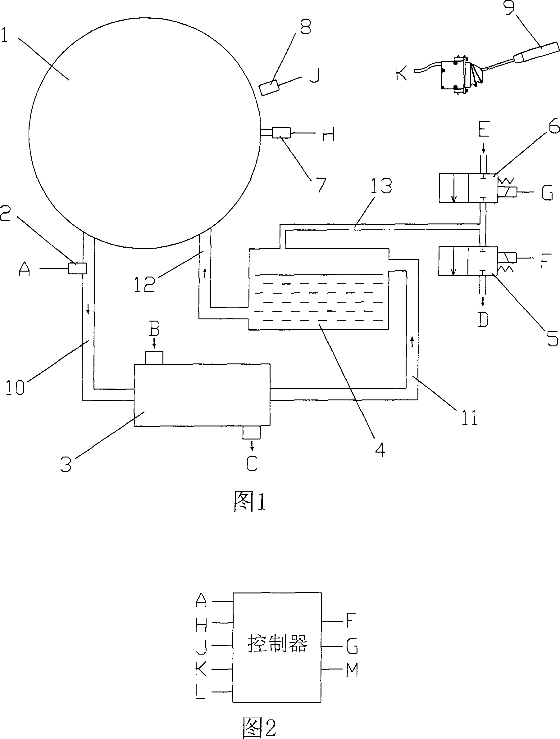
[0026] The present invention will be described in further detail below in conjunction with accompanying drawing:

[0027] Please refer to the accompanying drawings, in this embodiment, a pressure sensor 7 and a speed sensor 8 are installed on the side wall of the hydraulic retarder 1, and the oil outlet of the hydraulic retarder 1 is connected to the oil inlet of the heat exchanger 3. The mouth is connected with oil pipe 10, and temperature sensor 2 is arranged on oil pipe 10, and the oil outlet of heat exchanger 3 is connected with the oil inlet of accumulator 4 with oil pipe 11, and the oil outlet of accumulator 4 is connected with hydraulic slowdown The oil inlet of the gearbox 1 is connected with the oil pipe 12, the vent of the accumulator 4 is connected with the solenoid valve 5 and the solenoid valve 6 with the gas pipe 13, the other end of the solenoid valve 5 is connected to the exhaust chamber or the atmosphere, and the other end of the solenoid valve 6 is Connected ...


PUM


Abstract

The present invention relates to a hydraulic retarder control system and its control methods. The said hydraulic retarder connects with a heat exchanger with water inlet and outlet and accumulator with air vent, which makes up a liquid circuit; the air vent of accumulator distinctively equips with intake magnetic valve between compressed air through windpipe, and equips with air outlet magnetic valve; the pressure transducer and magnetic valve installed liquid circuit of hydraulic retarder and accumulator distinctively connect with control device by electricity, the gear switch connects with control device. The pressure value collected by the said control device compares with gear switch signal corresponding resetting value, when the differental value is bigger than fixed value, supplying electricity to the outlet magnetic valve to reduce pressure of the accumulator. When the differental value is lower than fixed one, supplying electricity to the intake magnetic valve to rise pressure of the accumulator, in order to keep the pressure in the cavity range, the hydraulic retarder can produce a stable inoment of resistance.

Description

technical field [0001] The invention relates to a control system and a control method of a hydraulic retarder. Background technique [0002] The hydraulic retarder is a rotation damping device, which uses its rotor to drive the liquid to rotate and impact the stator. At this time, the stator will also generate a reaction force through the liquid to act on the rotor, thereby hindering the rotation of the rotor. The hydraulic retarder can be used on the vehicle to play the role of auxiliary braking. At present, a few advanced large vehicles have been equipped with a hydraulic retarder. At present, hydraulic retarders generally use a control system composed of oil pumps, complex control valves, complex oil passages, controllers, etc., which is relatively difficult to manufacture and has high processing accuracy, so the cost is also high. In addition, its control accuracy is not accurate enough, and the maintenance difficulty is relatively large. Contents of the invention ...

Claims


Application Information

Patent Timeline
IPC IPC(8): F16F9/10
Inventor 凌兆蔚黄斌李天维闻维维
Owner 深圳市大为创新科技股份有限公司
Why Eureka
Try Eureka