Low-consumption uninterrupted power-supply system

A technology of power supply system and electrical connection, applied in power network operating system integration, information technology support system, current collectors, etc. The effect of improving operating efficiency, improving energy loss, and reducing the number of winding coils

Inactive Publication Date: 2007-11-21
DELTA ELECTRONICS INC
View PDF0 Cites 14 Cited by
  • Summary
  • Abstract
  • Description
  • Claims
  • Application Information

AI Technical Summary

Problems solved by technology

[0019] The main purpose of the present invention is to provide an uninterruptible power supply system with low power consumption. In the power supply mode of the energy storage device, the DC voltage output by the energy storage device is boosted by a DC-DC converter, After being converted into an AC voltage, it is directly transmitted to the load and the first winding coil of the transformer, and the second winding coil of the transformer will respond to the first AC voltage transmitted to the first winding coil to induce and output a second AC voltage, so that the second AC The voltage adjusts the value of the first AC voltage transmitted to the load in response to the connection state between the second switch group and the second winding coil, and releases the electric energy stored in the capacitive element of the load through the energy feedback circuit or converts the The electric energy released by the capacitive element of the load is recovered to the energy storage device for charging, thereby solving the energy loss caused by the switching of the switch of the known converter, and a large-area heat dissipation device is required to be attached to the switch, and the transformer is bulky. Copper wires will lose a lot of power during operation, which makes the operating efficiency of the entire uninterruptible power supply system poor and other disadvantages

Method used


Image

  • Low-consumption uninterrupted power-supply system
  • Low-consumption uninterrupted power-supply system
  • Low-consumption uninterrupted power-supply system

Examples


Embodiment Construction

[0062] Some typical embodiments embodying the features and advantages of the present invention will be described in detail in the ensuing description. It should be understood that the present invention can have various changes in different embodiments, all of which do not depart from the scope of the present invention, and the description and reference signs therein are used for illustration in nature and not for limiting the present invention. invention.

[0063]Please refer to Fig. 3 (a), which is a schematic diagram of the circuit structure of the uninterruptible power supply system of a preferred embodiment of the present invention. Provided voltage, the uninterruptible power supply system 40 includes a first transfer switch group 41, a second transfer switch group 42, a transformer 43, an energy storage device 47, a DC-DC converter 48, a converter 49 and a rectifier 44, an inductor L , an energy feedback circuit 451, a grounding terminal 452, a charging circuit composed ...


PUM


Abstract

The invention comprises: a controller; a first diverter switch group; a second diverter switch group; a first winding coil of the transformer connected to the load and the first diverter switch group; a secondary winding coil connected to the second switch group; a energy storage device; a power feedback circuit; a DC to DC converter used for boosting the DC voltage outputted from the energy storage device; a current transformer used for making a boosted DC voltage to sense a first AC voltage in order to output a second AC voltage, and making the second AC voltage to response the connection state between second diverter switch group and the second winding coil in order to adjust the value of first AC voltage transmitted to the load so as to provide a voltage meeting the running requirement of load.

Description

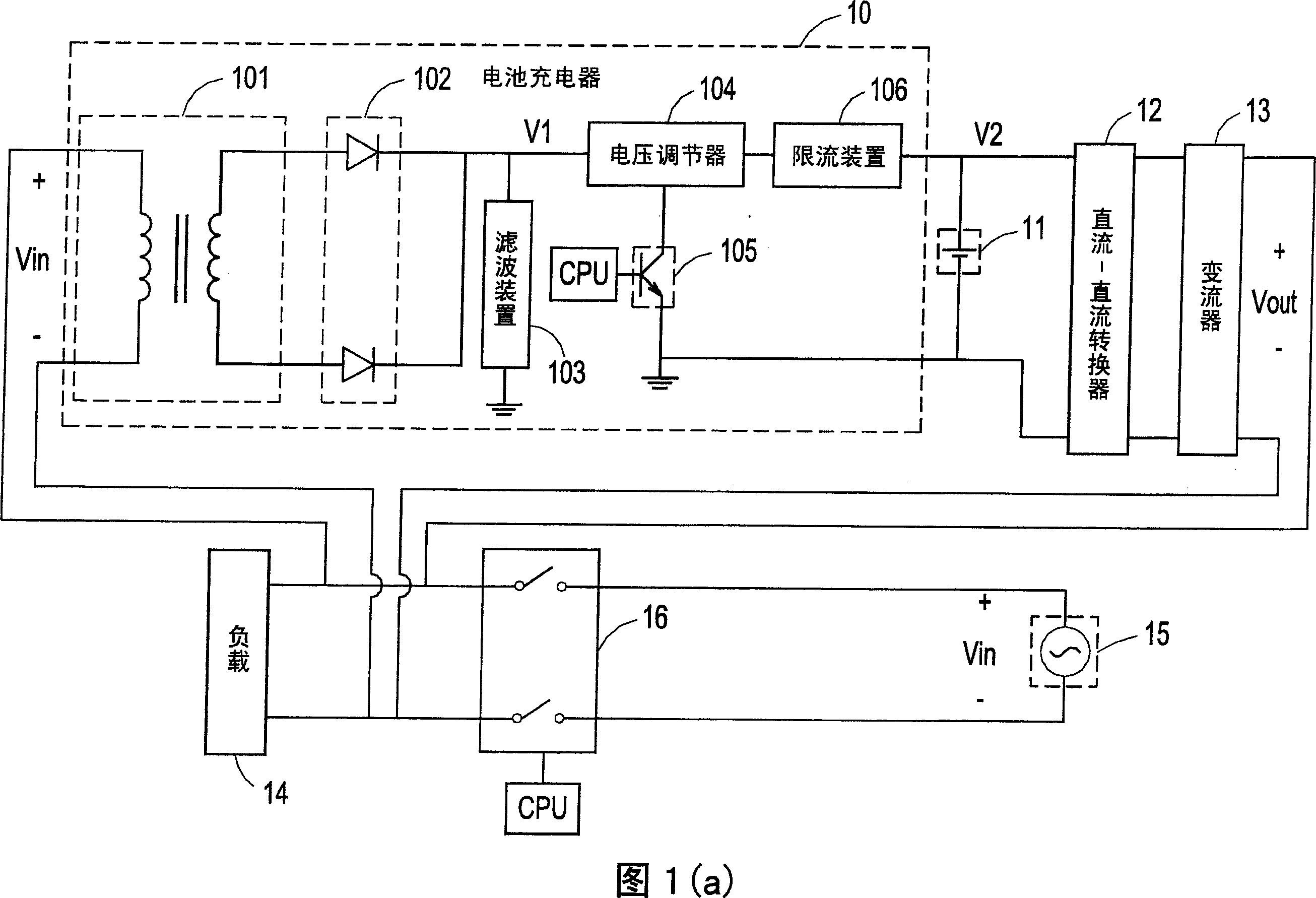
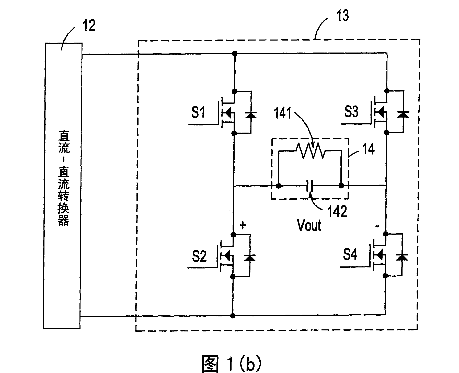
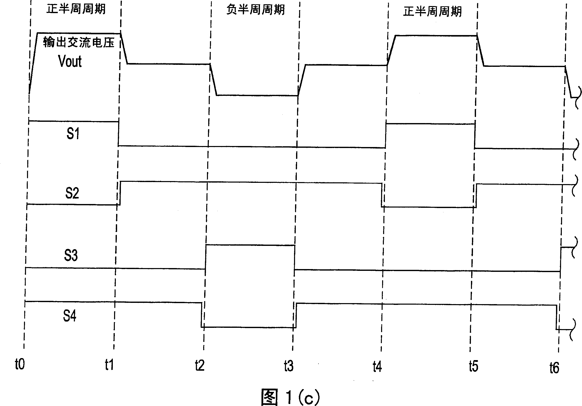
technical field [0001] The invention relates to a power supply system, in particular to an uninterrupted power supply system with low power consumption. Background technique [0002] An uninterruptible power supply system (Uninterruptible Power Supply, UPS) is a device connected between a power supply and a load. The power supply can be directly a commercial ACpower supply or a converted alternating current (AC) , the main purpose of the uninterruptible power supply system is to provide the energy required for the load operation in an emergency when the power supply is abnormal, so as to ensure the normal operation of the load. [0003] Please refer to Fig. 1(a), which is a schematic circuit diagram of a known uninterruptible power supply system. As shown in the figure, the uninterruptible power supply system mainly includes a battery charger 10, a battery module 11, a DC-DC converter 12, and a converter (inverter) 13 and switch group 16 are used to transmit the voltage of ...

Claims


Application Information

Patent Timeline
IPC IPC(8): H02J7/00H02J7/10H02J9/06
CPCY02B70/30Y04S20/20
Inventor 李嘉祥
Owner DELTA ELECTRONICS INC
Why Eureka
Try Eureka