Apparatus and method for reducing interference

An electronic device, technology for interfering signals, applied in the field of devices and methods for reducing interference

Inactive Publication Date: 2007-11-21
UNILEVER NV
View PDF6 Cites 36 Cited by
  • Summary
  • Abstract
  • Description
  • Claims
  • Application Information

AI Technical Summary

Problems solved by technology

When used in combination with MRI, e.g. fMRI, along with any such electrophysiological measurement, the same problem arises

Method used


Image

  • Apparatus and method for reducing interference
  • Apparatus and method for reducing interference
  • Apparatus and method for reducing interference

Examples


Embodiment Construction

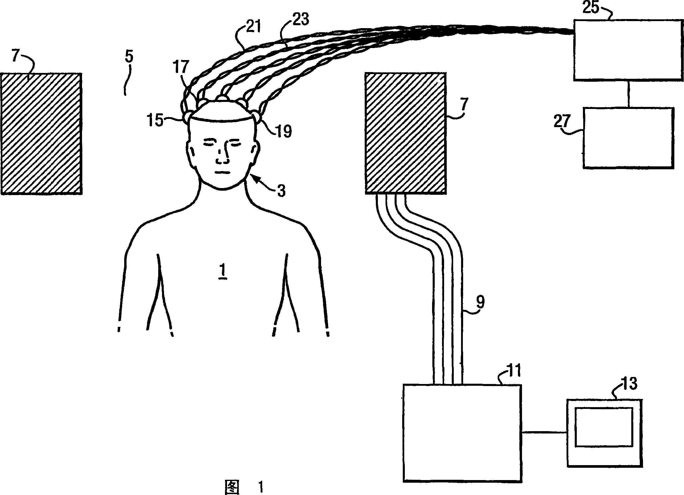
[0141] Figure 1 shows a basic fMRI and EEG system in which the apparatus and methods of one or more embodiments of the present invention may be employed.

[0142] As shown in FIG. 1 , the detection object 1 is arranged such that the head 3 of the detection object is located inside the fMRI coil unit 7 carrying the magnetic field winding and the radio frequency coil. These coils and windings are energized by a plurality of wires 9 etc. connecting the coil unit 7 to the operating circuit 11 . The operation circuit unit is connected to the storage and display unit 13, thereby arbitrarily storing, displaying and printing the MRI scan chart.

[0143] A plurality of electrodes 15 , 17 , 19 etc. for obtaining EEG signals are connected to the scalp of the test subject 1 . As will be described in more detail below, one of the electrodes 19 is the "reference electrode". The signals from the electrodes 15, 17, 19, etc. are transmitted to the EEG control unit 25 through the wires 21, 23...


PUM


Abstract

An electronic apparatus for reducing interference in a desired signal, the apparatus comprising: (a) a plurality of measurement signal lines, each connected to a respective measurement signal electrode; and (b) one or more reference signal lines, each connected to respective one or more reference electrodes; each of said measurement signal lines or a respective group of said measurement signal lines being associated by being in close physical proximity with a respective one of said reference signal lines for a substantial part of their lengths, so that each measurement signal line or signal line group with its corresponding reference signal line forms a measurement signal line or measurement signal line group / reference signal line pair, said electronic apparatus further comprising subtraction means for subtracting an interference on each reference signal line from an interference signal on the associated measurement signal line or from each measurement signal line in the measurement signal line group in that measurement signal line or measurement signal line group / reference signal line pair; wherein at least one of the measurement signal electrodes is arranged to be in direct electrical connection with a subject and at least one of the reference signal electrodes is arranged to be in close physical proximity but not in direct electrical contact with the subject.

Description

technical field [0001] The invention relates to an electronic method and device for reducing interference in a signal, wherein the interference is of a large magnitude for the data components to be extracted from the signal. Although not exclusive, it is particularly suitable for reducing noise generated by electromagnetic fields in biopotential signal acquisition. It is also used in other applications such as semiconductor physics, for example, to obtain electrical signals in the presence of large noise components due to large changes in magnetic fields. Background technique [0002] Functional magnetic resonance imaging (fMRI) is widely used in medical and non-medical imaging to obtain spatial images of "slices" through the brain. In the medical field, Magnetic Resonance Imaging (MRI) is used to identify sites of damage such as restricted blood flow or tumors. Outside of medicine, for example, in cognitive neuroscience, fMRI has become a useful tool for examining the bra...

Claims


Application Information

Patent Timeline
Patent Type & Authority Applications(China)
IPC IPC(8): A61B5/04A61B5/055A61B5/0428A61B5/0478A61B5/308G01R33/48H03F1/34H03F3/21H03F3/26H03F3/45H03H1/00
CPCA61B5/04004A61B5/0476A61B5/0496G01R33/4806H03F1/34H03F3/211H03F3/26H03F3/45475H03F2200/321H03F2200/534H03F2203/45138H03F2203/45526H03H1/0007A61B5/055A61B2562/222A61B5/30A61B5/398A61B5/369
Inventor W·J·R·邓希思
Owner UNILEVER NV
Why Eureka
Try Eureka