
CAN bus based electric energy quality real-time monitoring and evaluation system

A CAN bus, power quality technology, applied in the direction of electrical signal transmission system, measurement of electrical variables, signal transmission system, etc., can solve the problems of system paralysis, poor flexibility, low overall efficiency, etc., to reduce the requirements of hardware circuits, enhance Reliability, effect of improving error

Inactive Publication Date: 2007-11-28
SOUTH CHINA UNIV OF TECH
View PDF0 Cites 24 Cited by
  • Summary
  • Abstract
  • Description
  • Claims
  • Application Information

AI Technical Summary

Problems solved by technology

[0003] Offline portable instruments can only perform limited data acquisition and recording functions with human participation, and cannot provide rich and satisfying storage and historical data analysis functions
[0004] The stand-alone industrial computer method has little consideration in the 3-phase real-time acquisition and analysis, the working method is unreliable, and the collected and analyzed data cannot be transmitted to the control center for analysis and storage, so as to facilitate future data comparison analysis and data mining
[0005] The master-slave method based on RS232 / 485 simple network communication has many shortcomings: there can only be one master node on a network, and it is impossible to form a multi-master or redundant system. Once the master node fails, the entire system will be paralyzed; The data transmission efficiency is low and the flexibility is poor, which is the fatal weakness in the occasions with high real-time requirements; the RS485 specification is adopted in the physical layer, and the SDLC protocol is used in the link layer, the overall efficiency is low, especially the error handling ability is not good powerful

Method used

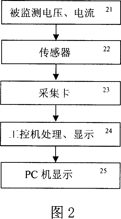
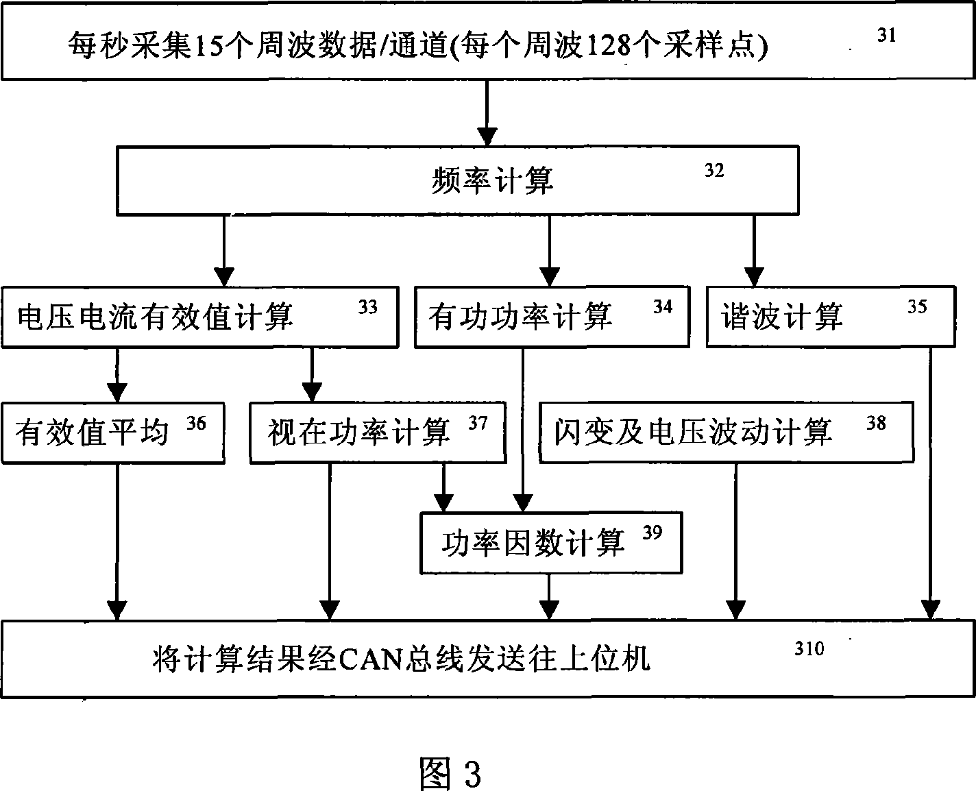

Image

  • CAN bus based electric energy quality real-time monitoring and evaluation system
  • CAN bus based electric energy quality real-time monitoring and evaluation system
  • CAN bus based electric energy quality real-time monitoring and evaluation system

Examples


Embodiment 1

[0029] Example 1: Detection and analysis of power quality in wind farms

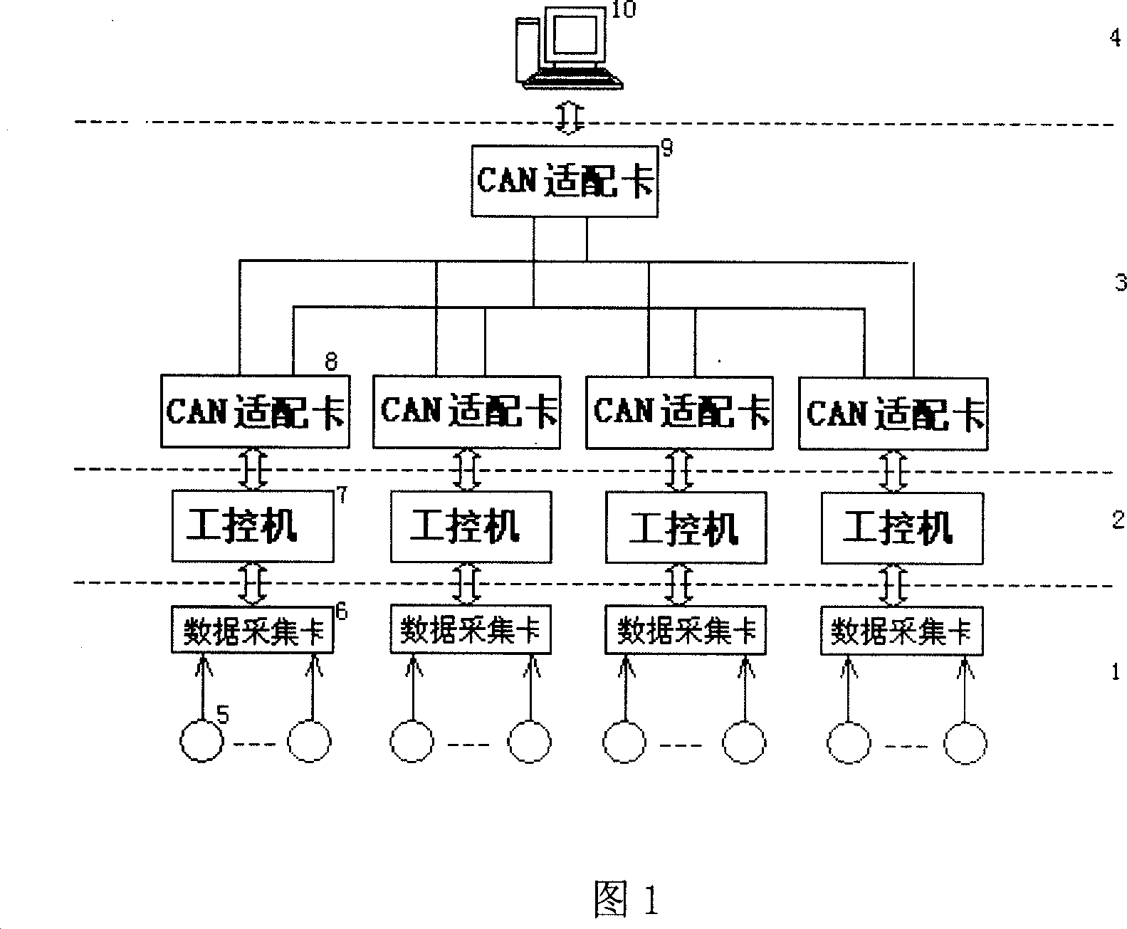
[0030] As Fig. 1 is the system structural diagram of a kind of power quality real-time monitoring and evaluation system based on CAN bus of the present invention, it is by the first layer data acquisition layer 1, the second layer data processing layer 2, the third layer data transmission layer 3 and The fourth layer user layer 4 consists of a total of four layers of network structure;

[0031] The data acquisition layer 1 is composed of multiple data acquisition groups, and each data acquisition group includes a sensor 5 , a terminal board, and a data acquisition card 6 . The sensor 5 converts the three-phase voltage and three-phase current data output by the monitored wind power generator into a standard 0-5V voltage, and then connects with the data acquisition card 6 through the connection terminal board, and the sampling frequency is realized by the acquisition card 6. 6.4kHz basic synchronous high-...


PUM


Abstract

The invention discloses a real-time monitoring and estimating system of power quality based on CAN bus for electric system and each class of power distribution system, which comprises the following network structures: data gathering layer as the first layer, which groups multiple stations to manage and transmits all the electric power network signal into standard voltage to the data gathering card; data disposing layer as the second layer, which converses the electric parameter by data gathering layer to realize the calculation and analysis of electric quality such as voltage fluctuation, harmonic analysis, flicker and so on; data transmitting layer as the third layer, which utilizes CAN bus to establish high-reliability opened data communicating circuit and realizes the conversion of order and data between middle control chamber PC set and working control machine; user layer as the fourth layer, which builds friend operational interface to provide display, storage, analysis and estimation function of the monitored data and makes the user to observe real-time data of wind electric-field operation directly.

Description

technical field [0001] The invention relates to a real-time monitoring and evaluation technology of electric energy quality, which is mainly applicable to the real-time monitoring and evaluation of electric energy quality of power systems and power distribution systems at all levels. Background technique [0002] At present, the existing power quality monitoring system products can be roughly divided into three categories: offline portable instruments, stand-alone industrial computer mode and master-slave mode based on RS232 / 485 simple network communication. [0003] Offline portable instruments can only perform limited data acquisition and recording functions with human participation, and cannot provide rich and satisfying storage and historical data analysis functions. [0004] The stand-alone industrial computer method has little consideration in the 3-phase real-time acquisition and analysis, the working method is unreliable, and the collected and analyzed data cannot be...

Claims


Application Information

Patent Timeline
Patent Type & Authority Applications(China)
IPC IPC(8): G08C19/00G08C19/02G01R13/00H04L12/28
Inventor 吴捷吴晓朝杨金明黄飞龙周丹莹
Owner SOUTH CHINA UNIV OF TECH
Learn More