
Method for determining angular separation between two laser bean in concave surface holographic grating production light path

A technology of holographic grating and laser beam, which is applied in the field of spectroscopy, can solve the problems of inapplicability, and achieve the effect of easy implementation and low cost

Inactive Publication Date: 2007-12-05
CHANGCHUN INST OF OPTICS FINE MECHANICS & PHYSICS CHINESE ACAD OF SCI
View PDF0 Cites 10 Cited by
  • Summary
  • Abstract
  • Description
  • Claims
  • Application Information

AI Technical Summary

Problems solved by technology

It can be seen that the traditional method of measuring angle or angular displacement is not suitable for determining the angle between two laser beams in the optical path of concave holographic grating

Method used


Image

  • Method for determining angular separation between two laser bean in concave surface holographic grating production light path
  • Method for determining angular separation between two laser bean in concave surface holographic grating production light path
  • Method for determining angular separation between two laser bean in concave surface holographic grating production light path

Examples


Embodiment Construction

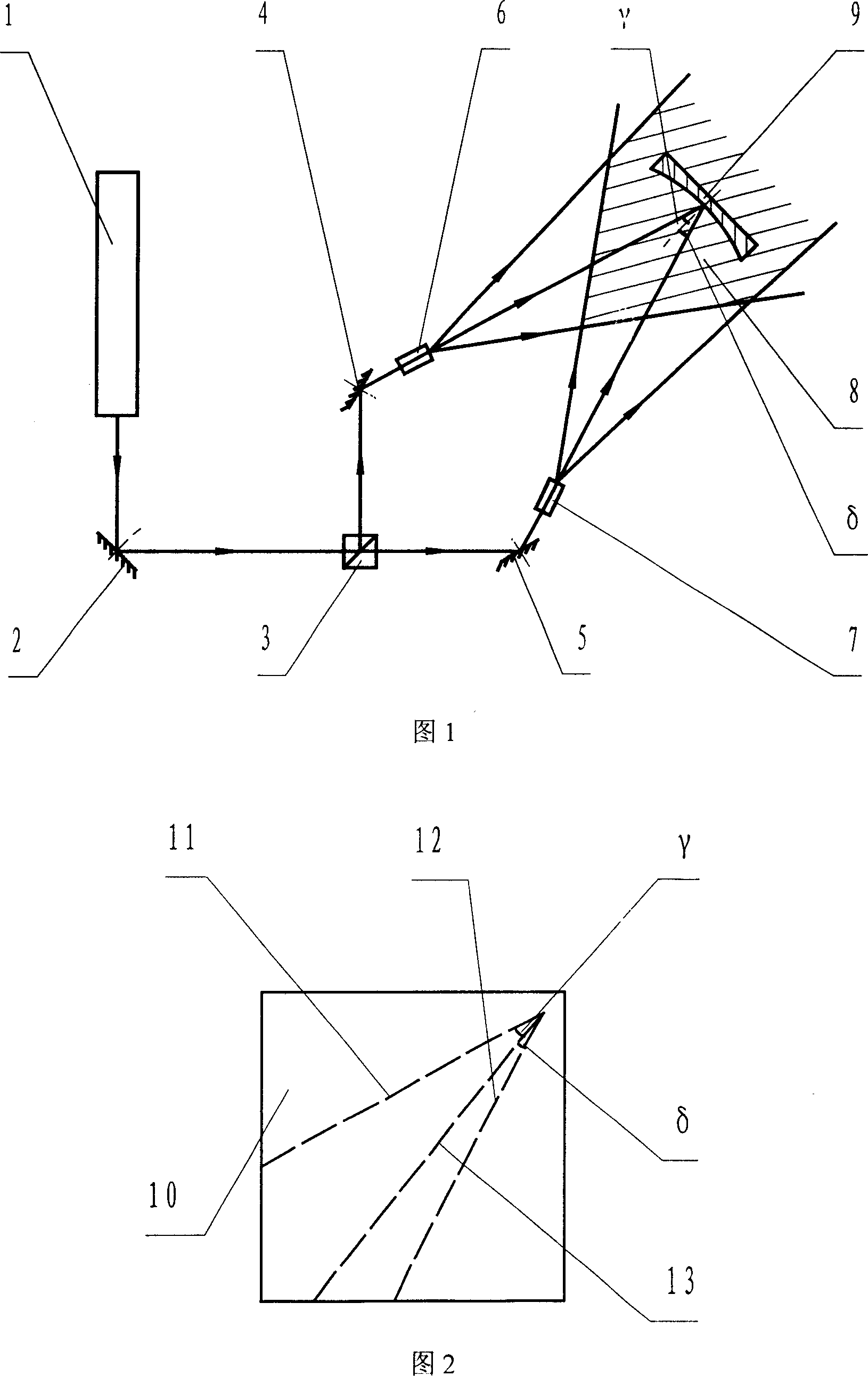
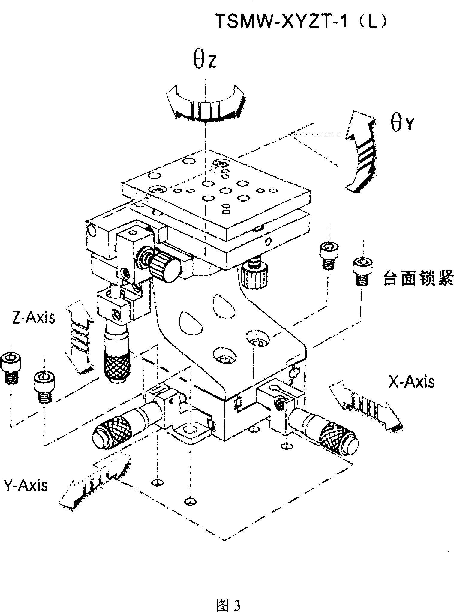
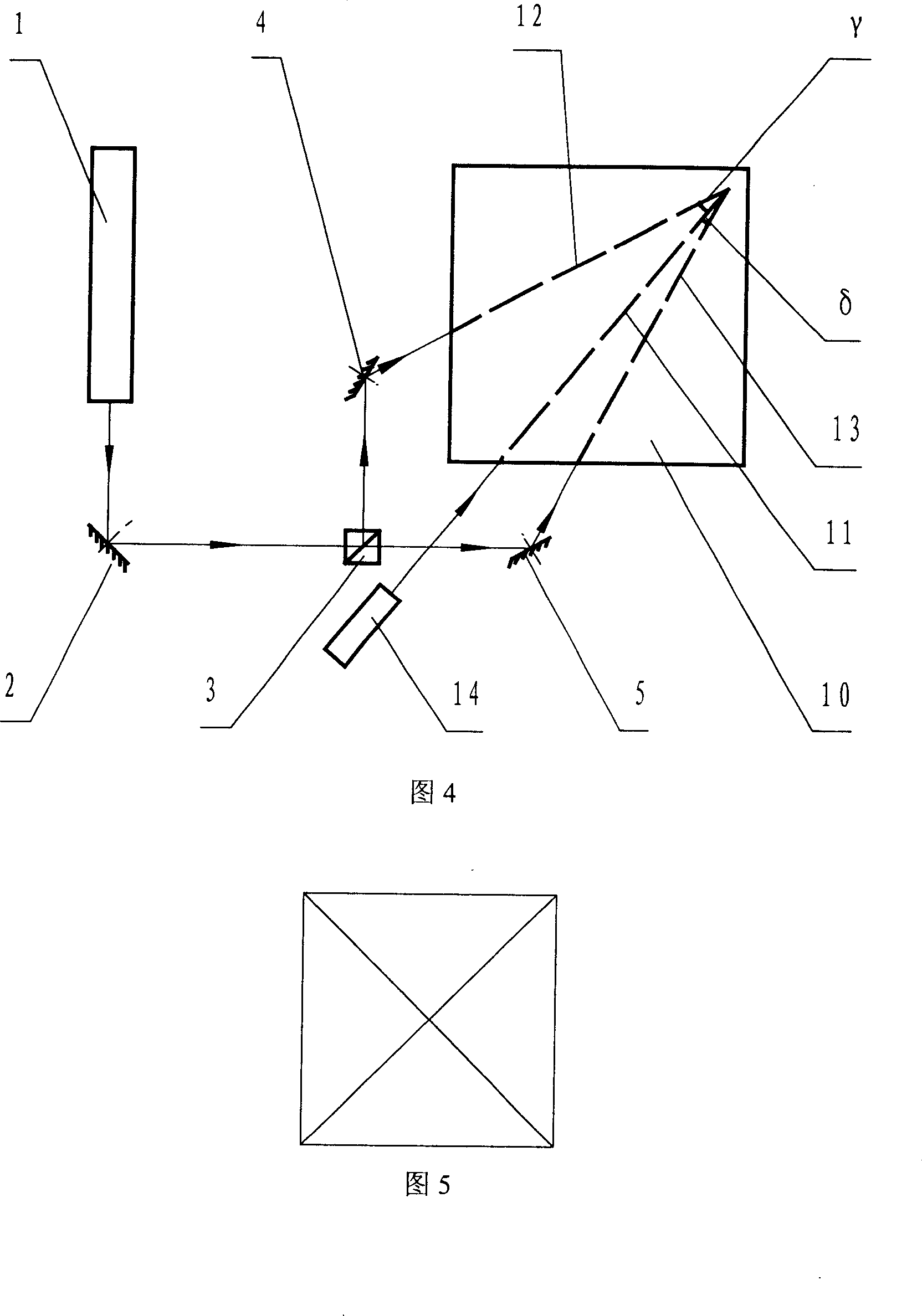
[0014] The present invention is implemented according to the established first, second, third and fourth four method steps. Light source 1 uses Kr + The laser has a wavelength of 413.1nm; the plane mirrors 2, 4 and 5 are aluminum-coated mirrors on glass substrates; the half-mirror half-mirror 3 is a double-glued glass prism; the pinhole filters 6 and 7 are composed of a microscope objective lens and a pinhole; The concave holographic grating blank 9 adopts K9 optical glass, and the photoresist coated on the K9 optical glass is Shipley 1805 type photoresist produced in Japan; the output wavelength of the He-Ne laser 14 is 632.8nm; It is a transparent plexiglass substrate; large flat

[0015] The angle lines 11, 12 and 13 on the plate are precisely inscribed using computer control.


PUM


Abstract

The invention discloses an affirming method of separation angle of two laser beams in the concave holographic grating making optical path in the spectrum technical domain, which comprises the following steps: 1. establishing a set of exposure device of concave holographic grating; 2. making a large plane board with angle line; 3. placing a He-Ne laser and large plane board in the optical path of exposure device; coincidencing main optical axle of ray from plane reflective lens and He-Ne laser and large plane board on the angle line separately; 4. affirming the position of blank of concave holographic grating; coincidencing crossing position of main optical axle of three laser beams and the central point of blank of concave holographic grating. The invention has directly important value for making high-quality concave holographic grating.

Description

1. Technical field [0001] The invention belongs to the field of spectrum technology and relates to a method for determining the included angle between two laser beams in the light path for making a concave holographic grating. 2. Background technology [0002] The concave holographic grating is a multi-band spectroscopic device used in the visible and ultraviolet regions. Using it can reduce the size of the spectroscopic instrument, reduce the number of components, eliminate the astigmatism of the optical system, and improve the imaging quality, resolution and testing of the optical instrument. precision. [0003] In the design process of the concave holographic grating, the Fermat principle is applied to the Seya-Namioka imaging system, and the optical path expansion method is used to correct the aberration of the optical system. Through calculation, the wave source point of the recorded spherical wave and the center of the concave holographic grating blank can be obtained....

Claims


Application Information

Patent Timeline
Patent Type & Authority Applications(China)
IPC IPC(8): G03H1/04G02B5/18
Inventor 李文昊巴音贺希格齐向东李英海
Owner CHANGCHUN INST OF OPTICS FINE MECHANICS & PHYSICS CHINESE ACAD OF SCI
Learn More