Passive optical network system and method of optical routing device and application optical routing device

A technology of passive optical network and optical distribution network

Active Publication Date: 2007-12-12
HUAWEI TECH CO LTD
View PDF1 Cites 20 Cited by
  • Summary
  • Abstract
  • Description
  • Claims
  • Application Information

AI Technical Summary

Problems solved by technology

[0009] Since the uplink and downlink wavelength pairs of ONUs of different operators are not uniform, when users choose different operators, they need to replace ONUs, which brings a lot of trouble to users and virtually limits the freedom of user choice;
[0010] Because the operator may lease different wavelength pairs in different cells, the operator must stock multiple types of ONUs, which increases the inventory burden of the operator and limits the service distribution of the operator;
[0011] Since terminal manufacturers need to produce various types of ONUs, the total amount of mass production of various types of ONUs is limited, which is not conducive to the reduction of ONU costs

Method used


Image

  • Passive optical network system and method of optical routing device and application optical routing device
  • Passive optical network system and method of optical routing device and application optical routing device
  • Passive optical network system and method of optical routing device and application optical routing device

Examples


Embodiment Construction

[0035] Embodiments of the present invention will be described in detail below in conjunction with the accompanying drawings.

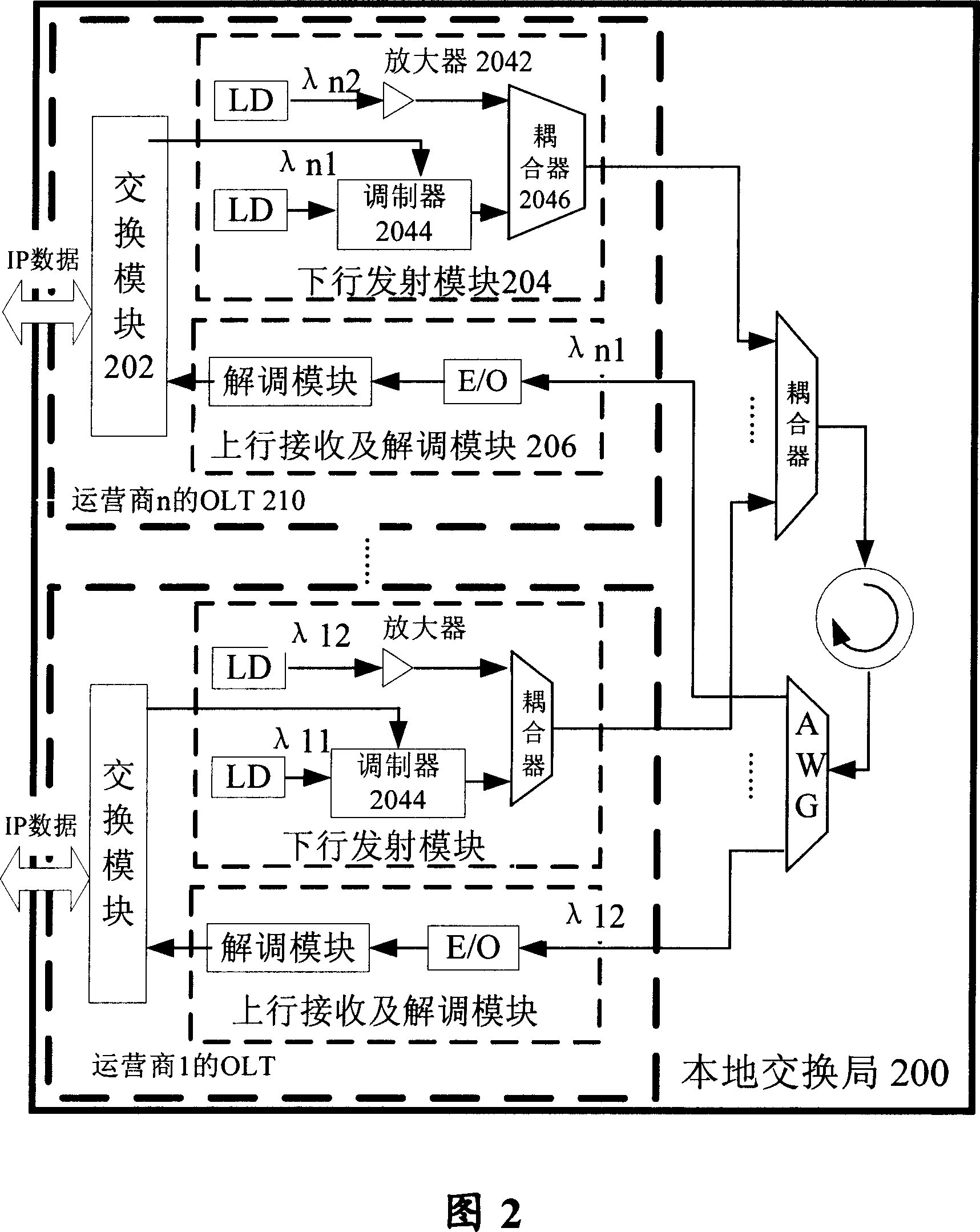
[0036] Fig. 2 shows a functional schematic diagram of an optical line terminal according to an embodiment of the present invention. As shown in FIG. 2, the local exchange 200 includes optical line terminals (hereinafter referred to as OLTs) of a plurality of operators. Since each OLT has the same structure, the following only uses the OLTn of operator n as an example for illustration. OLTn 210 includes: switching module 202, used for data exchange with the upper-level network; downlink transmitting module 204, connected to switching module 202, used to output two downlink lights with different wavelengths, wherein one downlink light λn1 is used to carry For the downlink data from the switching module 202, the other downlink light λn2 is unmodulated light without carrying data, because the unmodulated light has a relatively large loss when passing thro...


PUM


Abstract

The invention discloses an optical route device, which can output the input optical signal with different wavelength at arbitrary output end, and it includes: uniting / splitting wave device, which is used to unite and split the received optical signal; several splitters, and one port connects with several second uniting / splitting wave devices, which is used to distributing / combining the received optical signal; and routing device, connects with ports of several splitters, which is used to switch between the different output ports, and the optical signal can be sent to any output ports. The invention also discloses wireless optical network system and method which use the optical route device. Using the invention, it can realize the general purpose of optical network unit, and it is convenient for providing service for vendor.

Description

technical field [0001] The present invention relates to a passive optical network system, and more specifically, the present invention relates to a passive optical network system, which can arbitrarily route optical signals of different wavelengths to any colorless optical network unit. Background technique [0002] At present, many Internet services are accessed through dial-up modems, asymmetric digital line subscriber lines (ADSL), cable modems (CM), VDSL, etc. with rates ranging from 56K to several megabytes. However, in order to provide various services, such as high-quality video information services, VoD (Video on Demand) services, etc., data transmission requires a bandwidth of about 100 Mbps, and the above-mentioned access methods cannot meet the requirements. Therefore, The demand for laying access networks with optical fibers is growing rapidly. The Passive Optical Network (PON) is a user access network that can meet these new service requirements and is economica...

Claims


Application Information

Patent Timeline
Patent Type & Authority Applications(China)
IPC IPC(8): H04B10/00H04L12/56
CPCH04J14/02
Inventor 赵峻林华枫黄伟
Owner HUAWEI TECH CO LTD
Why Eureka
Try Eureka