Rockbolt construction drill method and tube component for rockbolt construction drill

A technology for the construction of tubular components and anchor rods, which is applied in the direction of drill pipes, drill pipes, casings, etc., which can solve the problems of slow work efficiency, complicated procedures, and large disturbance of the soil layer, and achieve simple structure, simple procedures, and good results.

Inactive Publication Date: 2007-12-19
曾庆义
View PDF1 Cites 9 Cited by
  • Summary
  • Abstract
  • Description
  • Claims
  • Application Information

AI Technical Summary

Problems solved by technology

[0003] The purpose of the present invention is to provide a drilling method and a drilling tool for bolt construction with simple procedure, high efficacy and good use effect, so as to solve the problem of complex procedures, slow work efficiency and damage to soil in existing bolt construction drilling methods. Problems such as large layer disturbance

Method used


Image

  • Rockbolt construction drill method and tube component for rockbolt construction drill
  • Rockbolt construction drill method and tube component for rockbolt construction drill
  • Rockbolt construction drill method and tube component for rockbolt construction drill

Examples


Embodiment 1

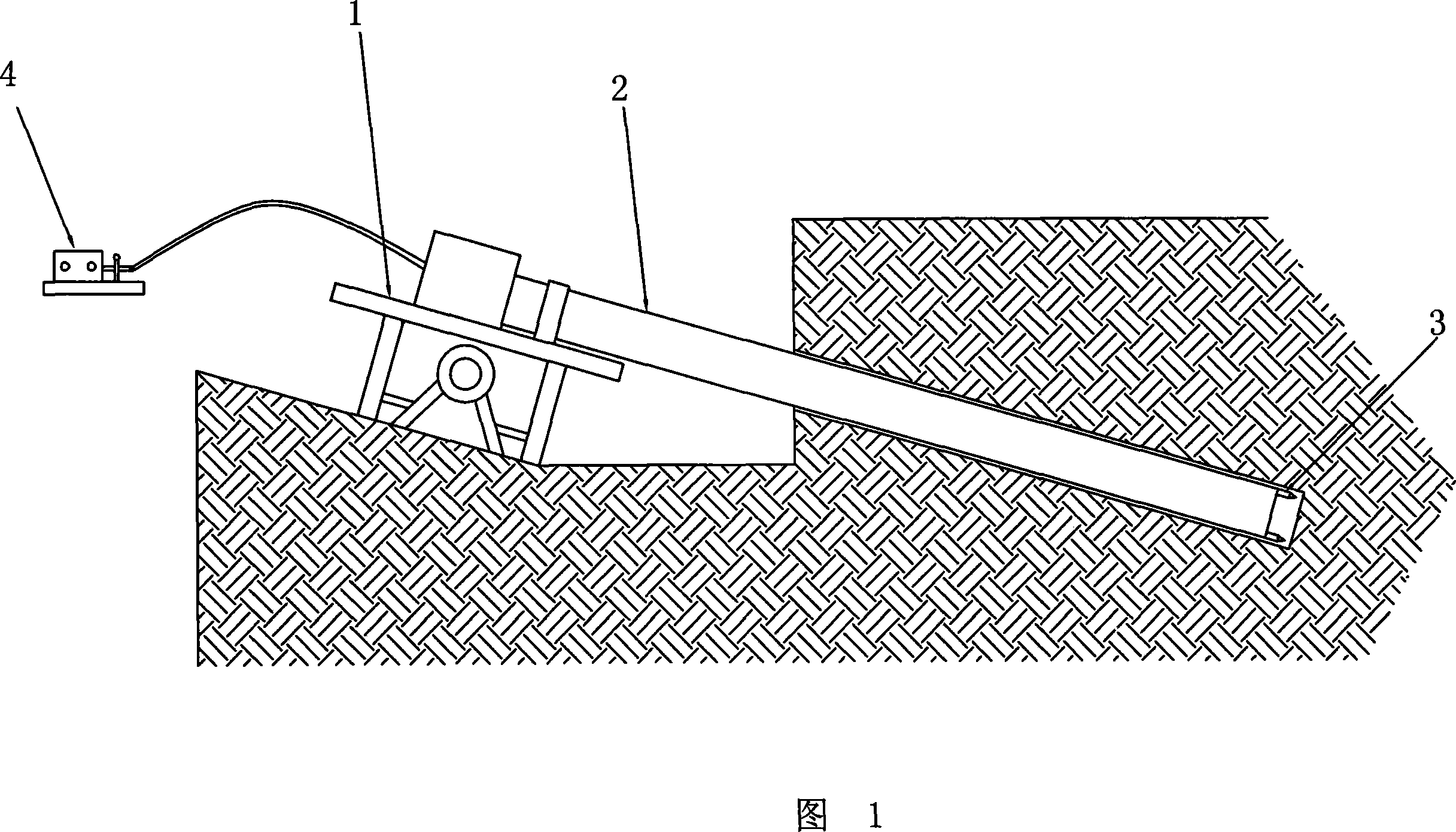
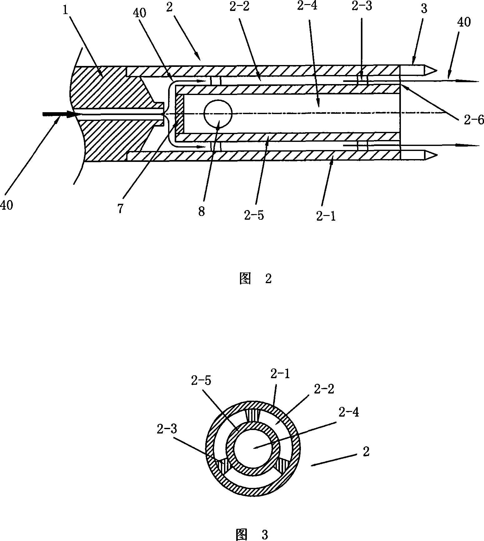
[0029] As shown in FIG. 1 , the present invention provides a tubular member 2 for anchor rod construction drilling, which is used to connect a drill bit 3 and a drilling machine 1, and is driven by the drilling machine 1 to carry out rotary drilling. As shown in FIG. 2 and FIG. 3 , the tubular member 2 includes an outer tube 2 - 1 , one end of which is connected to the joint of the drill 1 , and the other end is connected to the drill bit 3 . In the cavity in the outer tube 2-1, an inner tube 2-5 is also sleeved. The outer diameter of the inner tube 2-5 is smaller than the inner diameter of the outer tube 2-1, and there are several point-like supports 2-5 between them. 3 Support and fix it so that it forms an integral part without blocking the interlayer channel between the inner and outer tubes, and the interlayer channel formed between the inner wall of the outer tube 2-1 and the outer wall of the inner tube 2-5 constitutes the drainage channel 2 -2. During the drilling pro...

Embodiment 2

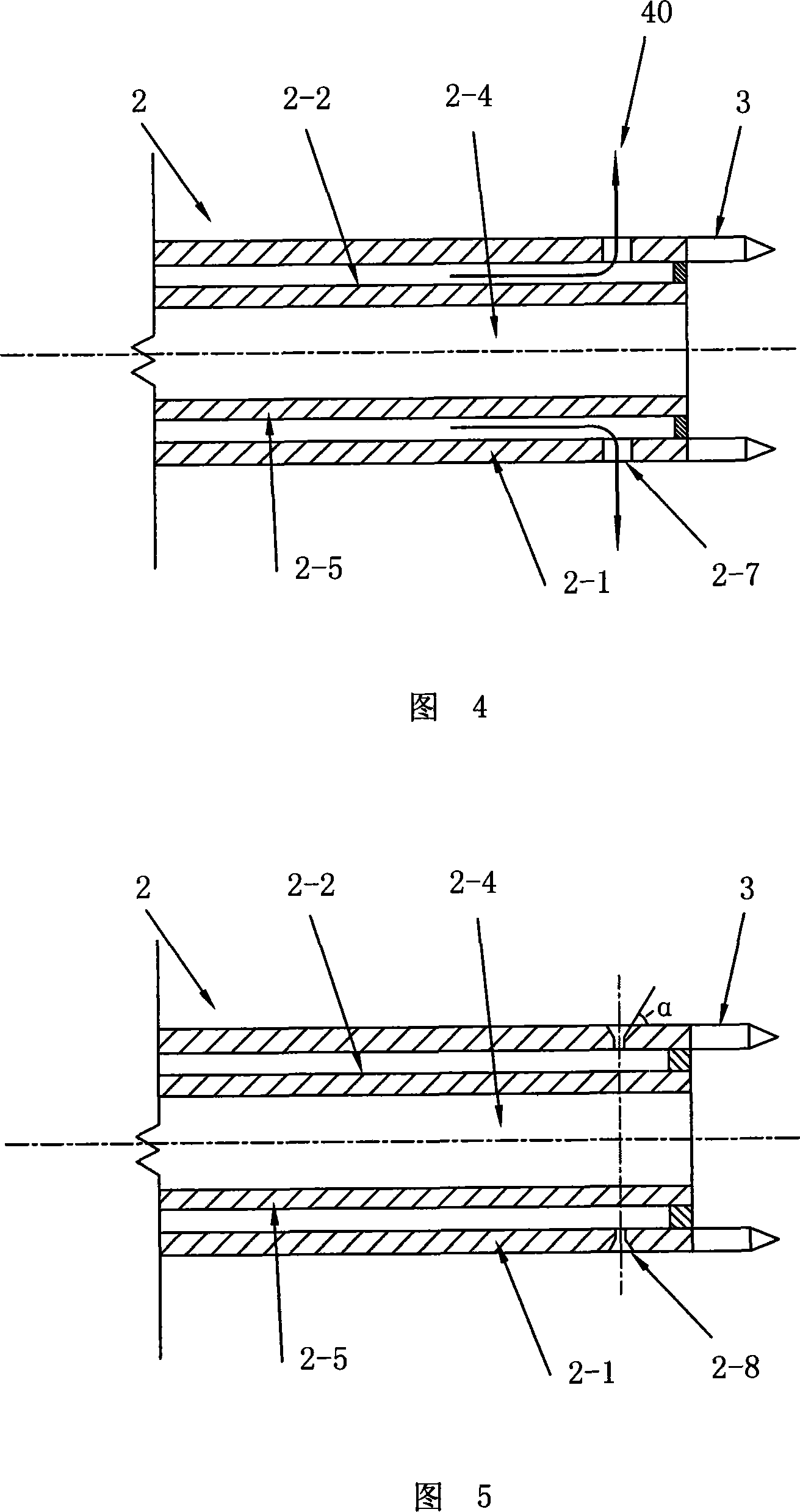
[0031]As shown in Fig. 4, the tubular member of this embodiment is also used to connect the drill bit 3 and the drilling machine 1, and is driven by the drilling machine 1 for rotary drilling. The tubular member 2 also includes an outer tube 2-1, one end of which is connected to the joint of the drilling machine 1, and the other end is connected to the drill bit 3, that is, the drill bit 3 is mounted on the front end of the tubular member 2. In the hollow channel of the outer tube 2-1, an inner tube 2-5 is also sleeved. The outer diameter of the inner tube 2-5 is smaller than the inner diameter of the outer tube 2-1, and the interlayer gap formed between the two forms a The drainage channel 2-2, the liquid 40 can be introduced into the drainage channel 2-2 through the drill 1. In this embodiment, one or more water outlets 2-7 or nozzles 2-8 (as shown in Figure 5 ) are provided on the front end wall of the outer pipe 2-1, and the water outlets 2-7 or nozzles 2- 8. It is either...

Embodiment 3

[0033] In this embodiment, the adopted tubular members and other supporting facilities are basically the same as in Embodiment 2, the difference is that the pump 4 of this embodiment adopts a high-pressure pump, and the pressure value of the liquid provided by the high-pressure pump is 0.5MPa~50Mpa between. In this embodiment, the high-pressure liquid flows out through the nozzle 2-8 or the water outlet 2-7 to form a high-pressure jet, which impacts the soil on the wall of the anchor hole, which can better roughen the wall of the hole and form an enlarged anchor hole. Greatly improve the frictional resistance of the anchor and improve the pullout resistance of the anchor. In particular, when the pullout force of the required bolt is large, a high pressure of 8-50Mpa can be used to form a larger enlarged head at the anchorage section. If the required pull-out resistance is not particularly large, a high pressure of 0.5-8Mpa can be used to roughen the hole wall, or form a small...


PUM


Abstract

The present invention relates to an anchor rod construction drilling method. Said method adopts drilling machine to drive tubular member whose front end is equipped with drill bit and make it rotation drive forwards, on the tubular member a flow-guiding channel is set, said flow-guiding channel can be used for transferring fluid to the drill bit; the described fluid or high-pressure fluid passed through the flow-guiding channel and transferred to the drill bit can be passed through said tubular member or fluid outlet or nozzle which is set on the drill bit and is perpendicular to the axis direction of drilled hole and flowed out, and can be used for acting on the hole wall of drilled hole, cleaning the hole wall of anchor hole and broaching the hole.

Description

【Technical field】 [0001] The invention relates to a drilling method for anchor rod construction and a construction tool applied to the construction method, in particular to a drilling method using a tubular member with a drill bit and a tubular member for anchor rod construction drilling applied to the method. member. 【Background technique】 [0002] Existing drilling methods for anchor rod construction use a drilling rig to drive a drill pipe or casing with a drill bit installed at the front end to drill. They all use the hollow channel of the drill pipe or casing to deliver liquid or mud to the drill bit. Control the transported liquid or mud well, so that it can be better cleaned and roughened the wall of the anchor hole, resulting in a reduction in the pullout resistance of the constructed anchor; second, the liquid or mud must be discharged through the drill pipe or casing. The gap between the pipe and the borehole wall, in this way, greatly disturbs the soil, especiall...

Claims


Application Information

Patent Timeline
Patent Type & Authority Applications(China)
IPC IPC(8): E21B17/00
Inventor 曾庆义
Owner 曾庆义
Why Eureka
Try Eureka