Pneumatic drying energy saving device

An energy-saving device and air-flow drying technology, which is applied to heating devices, drying, drying machines, etc., can solve the problems of poor economic benefits, unsolved problems, and low thermal efficiency, and achieve the effects of reducing coal consumption, simple structure, and high benefits

Inactive Publication Date: 2007-12-19
刘奇贤
View PDF0 Cites 5 Cited by
  • Summary
  • Abstract
  • Description
  • Claims
  • Application Information

AI Technical Summary

Problems solved by technology

The thermal efficiency is low, the coal consumption is high, the cost is high, and the economic benefit is poor
This problem has puzzled people for a long time, but it has not been solved

Method used


Image

  • Pneumatic drying energy saving device
  • Pneumatic drying energy saving device

Examples


Embodiment Construction

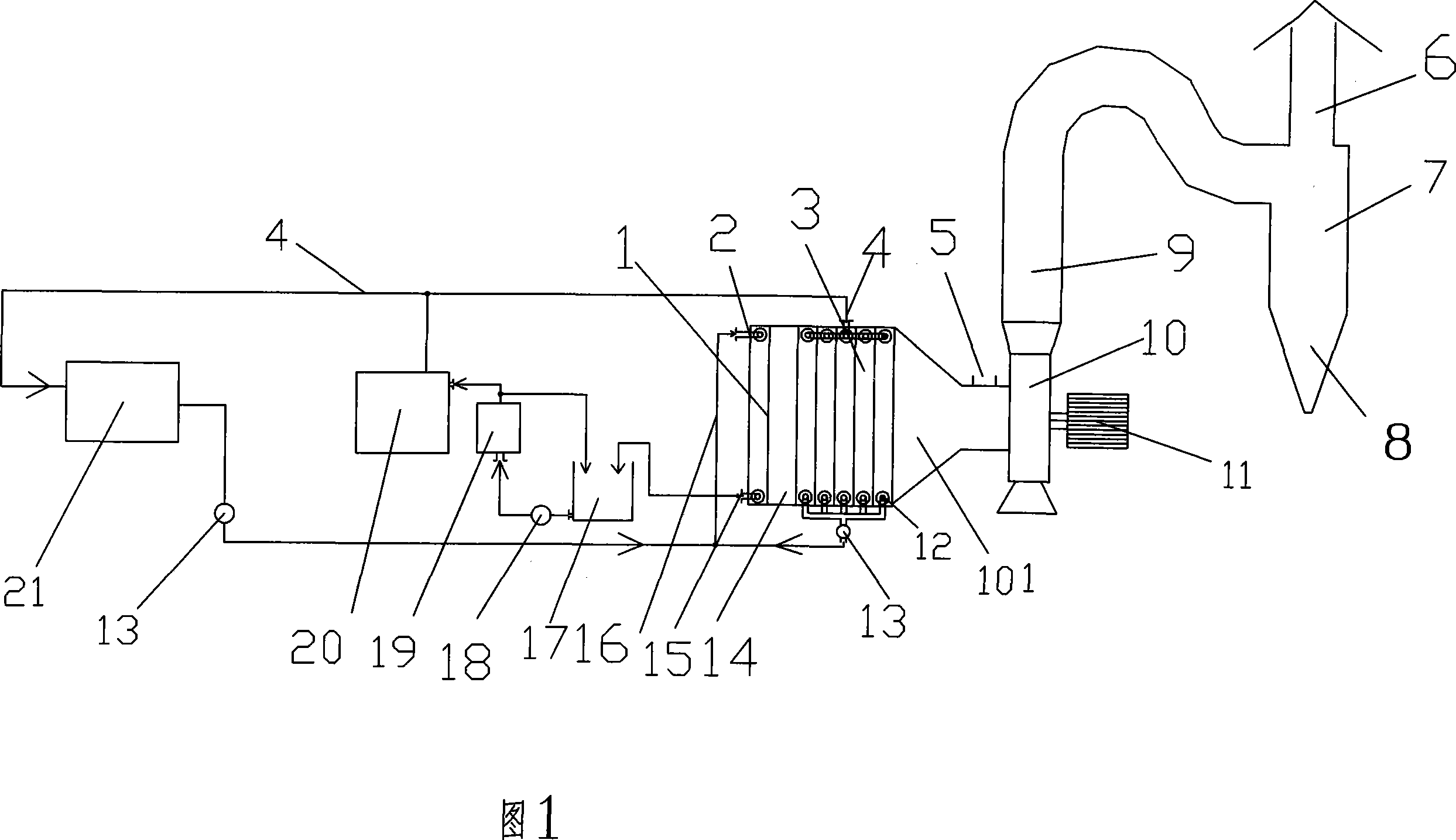
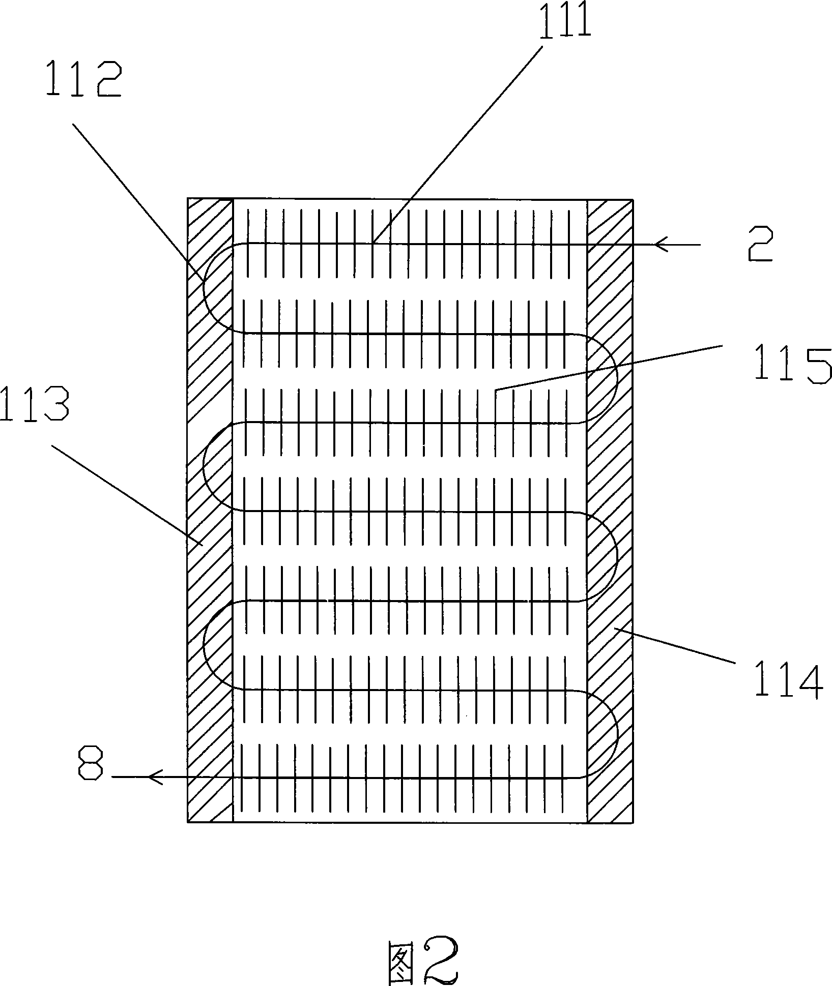
[0018] Referring to Fig. 1 and Fig. 2, the starch airflow drying energy-saving device includes a steam heating group 3 connected with the steam outlet pipe 4 of the boiler 20, the fan 10 is connected with the steam heating group 3 through a wind cover 101, and is provided with an inlet Feeder 5, air duct 9 and gas-solid separator 7 (can be the same as the prior art) (the blower fan is a suction type, and can also be blown in), and the air inlet side of the steam heating group 3 is provided with a recovery water waste heat The airflow preheater 1, the structure of the airflow preheater 1 is a radiator for recovering water waste heat, and an airflow channel is arranged between the radiators; the outlet pipe 8 of the airflow preheater 1 is connected with the circulating water return pipe of the boiler 20, and the airflow preheater The water inlet pipe 2 of 1 communicates with the water outlet pipe of the steam heating group 3. A steam trap 13 is provided in the communication pipe...


PUM


Abstract

An energy-saving device of air-steam drying is prepared as connecting fan to stream heating set and arranging material feeder and air duct as well as air-solid separator between said fan and steam heating set, setting residual-heat air stream preheater applying structure of heat radiator at air inlet side of steam heating set, connecting residual-heat recovery water pipe to water inlet pipe of air stream preheater and connecting water outlet of air stream preheater to circulation water-return pipe of boiler.

Description

technical field [0001] The invention relates to the technical field of airflow drying equipment, in particular to an airflow drying energy-saving device for powdery materials such as starch. Background technique [0002] At present, in the existing starch industry, the starch drying system is composed of a heating group consisting of heat sinks, a feeder, a fan, and an airflow net. Use heat sinks to generate hot air to dry materials. The production process adopts 6-7 heat sinks to form a heating group to heat the natural wind. The air supply pressure is generally maintained at about 6 kg, and the air temperature is maintained at about 150 degrees. The by-product fiber, germ, and protein powder in the starch production process are dried by tube bundles. Cooling water is produced during the drying process, and the cooling water is output through the trap. The temperature of the cooling water at the outlet of the trap is kept at about 95 degrees and entrains a certain amount ...

Claims


Application Information

Patent Timeline
Patent Type & Authority Applications(China)
IPC IPC(8): F26B23/10
CPCY02P70/10
Inventor 刘天友刘奇贤
Owner 刘奇贤
Why Eureka
Try Eureka