Exhaust emission control device and internal combustion engine equipped with the exhaust emission control device and particulate filter regenerating method

一种微粒过滤器、排气气体的技术,应用在排气处理装置的电控、排气装置、化学仪器和方法等方向,能够解决PM堆积量误判断、不能充分确保可靠性、增大等问题

Inactive Publication Date: 2007-12-19
YANMAR CO LTD
View PDF9 Cites 34 Cited by
  • Summary
  • Abstract
  • Description
  • Claims
  • Application Information

AI Technical Summary

Problems solved by technology

[0026] As mentioned above, in the conventional method for detecting the amount of PM accumulation, the reliability cannot be ensured sufficiently, so there is a possibility of misjudgment of the amount of PM accumulation in the filter
For example, in a situation where the PM accumulation amount is misjudged to have reached a predetermined amount (an amount that requires filter regeneration) irrespective of the fact that the actual PM accumulation amount is small, the regeneration operation is frequently performed, resulting in the need for the regeneration operation. The increase in energy (for example, in the case of filter heating by an electric heater, the power consumption increases), or the possibility of adversely affecting the life of the filter due to frequent filter heating
Conversely, when the actual PM accumulation amount has reached the above-mentioned specified amount, if it is misjudged that the PM accumulation amount has not reached the specified amount, the filter will be excessively clogged, and the exhaust pressure loss will increase, resulting in a drop in engine output and fuel consumption. Worsening attrition rate

Method used


Image

  • Exhaust emission control device and internal combustion engine equipped with the exhaust emission control device and particulate filter regenerating method
  • Exhaust emission control device and internal combustion engine equipped with the exhaust emission control device and particulate filter regenerating method
  • Exhaust emission control device and internal combustion engine equipped with the exhaust emission control device and particulate filter regenerating method

Examples


no. 1 approach

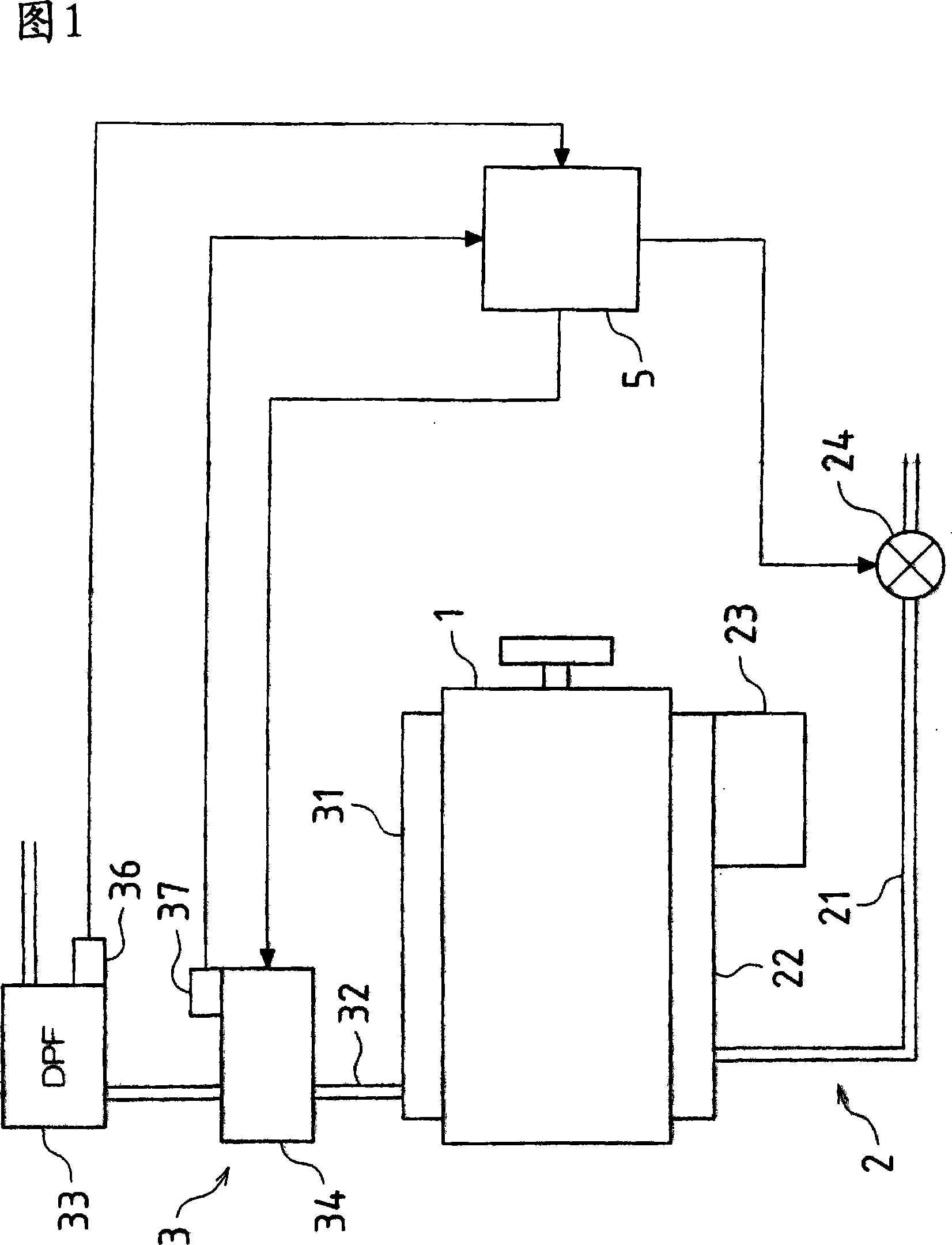
[0198] In the present embodiment, the air intake throttle device 24 and the exhaust temperature raising device 34 are controlled based on the PM accumulation amount inside the DPF 33 and the exhaust gas temperature. That is, when the controller 5 receives the PM accumulation amount detection signal from the PM accumulation amount detection sensor 36 and determines that the PM accumulation amount inside the DPF 33 exceeds a predetermined amount, and the controller 5 receives the PM accumulation amount detection signal from the exhaust gas temperature detection sensor 37 When it is determined that the exhaust gas temperature has not reached the above-mentioned temperature at which the regeneration operation can be performed (hereinafter, the case where these two conditions are satisfied is referred to as "the case where the exhaust gas temperature increase control start condition is satisfied"), By operating one or both of the air intake throttling device 24 and the exhaust tempe...

no. 2 approach

[0221] Next, a second embodiment will be described. This embodiment is a modified example related to the "limit value" which defines the limit of the air intake throttle amount in the above-mentioned first embodiment. Since other configurations and control operations are the same as those of the first embodiment, descriptions of the parts common to the first embodiment are omitted here.

[0222] As described above, when the amount of intake air is reduced by the air intake throttling operation of the air intake throttle device 24, the ignition timing of the air-fuel mixture is delayed. As a result, incomplete combustion occurs, and the amounts of CO and THC in the exhaust gas gradually increase. FIG. 6 shows the relationship between the meter-in amount and the concentrations of CO and THC in the exhaust gas. In this way, although in the region where the meter-in flow is relatively small, the increase ratio of the concentration of CO and THC relative to the increase in the me...

no. 3 approach

[0234] Next, a third embodiment will be described. In the present embodiment, an electric heater is used as the exhaust temperature raising device 34, and power supply to the electric heater 34 is directly performed by an alternator. Since other configurations and control operations are the same as those of the above-mentioned first embodiment and second embodiment, descriptions of parts common to the first embodiment and second embodiment are omitted here.

[0235] As shown in FIG. 10 , the engine according to this embodiment is provided with an alternator 61 that generates electricity by receiving the rotational driving force of the crankshaft on the side surface of the engine main body 1, and part of the electric power generated by the alternator 61 is supplied to the electric heater. (Exhaust heating device) 34. The ON / OFF switching of the power supply to the electric heater 34 is performed by the exhaust gas temperature increase control signal from the controller 5 as in...


PUM


Abstract

In an embodiment of an exhaust gas purification apparatus, when an accumulation amount of particulate matter in a DPF (33) exceeds a predetermined amount and an exhaust gas temperature of an engine is lower than a restoration operable temperature, an intake air amount reducing operation is executed by an air intake throttling device (24) provided for an air intake pipe (21) of the engine, and a heating operation is executed by an electric heater (34) provided upstream from the DPF (33), thereby increasing the exhaust gas temperature to the restoration operable temperature to start a restoration operation of the DPF (33).

Description

technical field [0001] The present invention relates to a particulate filter (hereinafter abbreviated as PM) provided in an exhaust system of an internal combustion engine typified by a diesel engine and capable of trapping particulate matter (Particulate Matter, hereinafter referred to as PM) in exhaust gas. filter), an internal combustion engine having the exhaust gas purification device, and a filter regeneration method. Background technique [0002] In recent years, in internal combustion engines installed in automobiles, etc., it is required to improve the purification of exhaust gas. In particular, in diesel engines, it is required to remove coal, etc. contained in exhaust gas in addition to reducing CO, HC, and NOx. PM. Therefore, a filter made of a porous material or the like is disposed on the exhaust passage of the engine, and the PM in the exhaust gas is captured by the filter. [0003] Since the filter is made of the porous material mentioned above, if the amou...

Claims


Application Information

Patent Timeline
Patent Type & Authority Applications(China)
IPC IPC(8): F01N3/02B01D53/94F02B37/12F02B37/18F02D9/02F02D9/04F02D21/08F02D23/00F02D41/02F02D41/22F02D43/00F02D45/00F02M25/07B01D46/42
CPCY02T10/42F01N3/0222F01N3/0235F01N13/009F02B37/18Y02T10/144F01N2240/16F01N2390/00Y02T10/47F01N2013/023F01N9/002F02D41/0002F02D2200/0812F01N2560/12F01N13/0093F01N2560/05F01N13/008F01N13/02F02D41/029F01N3/027Y02T10/12Y02T10/40F01N9/00B01D53/94F02B37/12B01D46/42
Inventor 原道彦西村章广冈田周辅北崎真人
Owner YANMAR CO LTD
Why Eureka
Try Eureka