Supercharge Your Innovation With Domain-Expert AI Agents!

Compression joint type elements and parts board, and method for connecting the board to experimental board

A component and crimping technology, which is applied in the field of crimping component boards and their access test boards, can solve the problems of reduced experimental efficiency and success rate, virtual welding and short-circuit faults, and large numbers, and saves experiments. Cost, reduced contact resistance, good shock resistance

Inactive Publication Date: 2007-12-26
黎荣昌
View PDF0 Cites 12 Cited by
  • Summary
  • Abstract
  • Description
  • Claims
  • Application Information

AI Technical Summary

Problems solved by technology

But practice has proved that in the electronic circuit experiment, the electronic components on the experiment board are not only numerous but also densely distributed, and it is very troublesome to solder the components on the experiment board. Soldering and short-circuit faults, the distribution of components and wiring is also very disordered, which is inconvenient for circuit testing and fault finding
In many cases, some components are relatively expensive, but after being soldered to the test board, it is difficult to remove them and reuse them, which causes a serious waste of resources.
Although the plug-in connection is easy to operate and the components can be reused, the durability of the contacts is not good, the anti-vibration ability is weak, and the contact performance is poor. Failures due to poor contact often occur, resulting in test failures
Especially for complex circuit experiments and development experiments of electronic products, due to too many and complicated components and circuits to be plugged in, the distribution of patch cords used to connect components will be disordered, and the contact contact is not firm enough, which is prone to occur due to the contact falling off. Find out the problem that it is difficult to eliminate the fault due to poor contact at multiple points at the same time, resulting in a decrease in the efficiency and success rate of the experiment, and an increase in the labor intensity of the experimenter
In addition, there are many components that do not provide sockets at all, and it is impossible to use the plug-in method to complete the experiment
[0004] In addition, the use of plug-in and welding methods to access components makes it impossible to arrange components and multi-layer wiring on both sides of the experiment board, resulting in poor splicing and expansion capabilities of the experiment board

Method used


Image

  • Compression joint type elements and parts board, and method for connecting the board to experimental board
  • Compression joint type elements and parts board, and method for connecting the board to experimental board
  • Compression joint type elements and parts board, and method for connecting the board to experimental board

Examples


Embodiment Construction

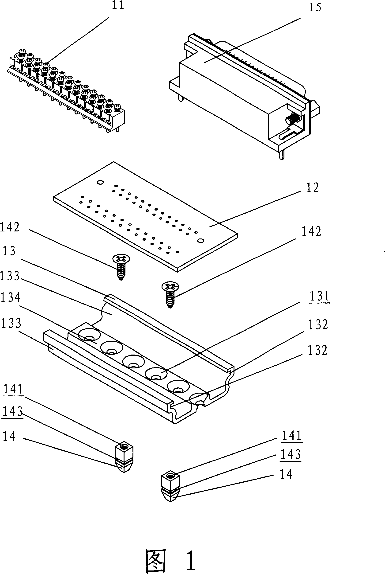
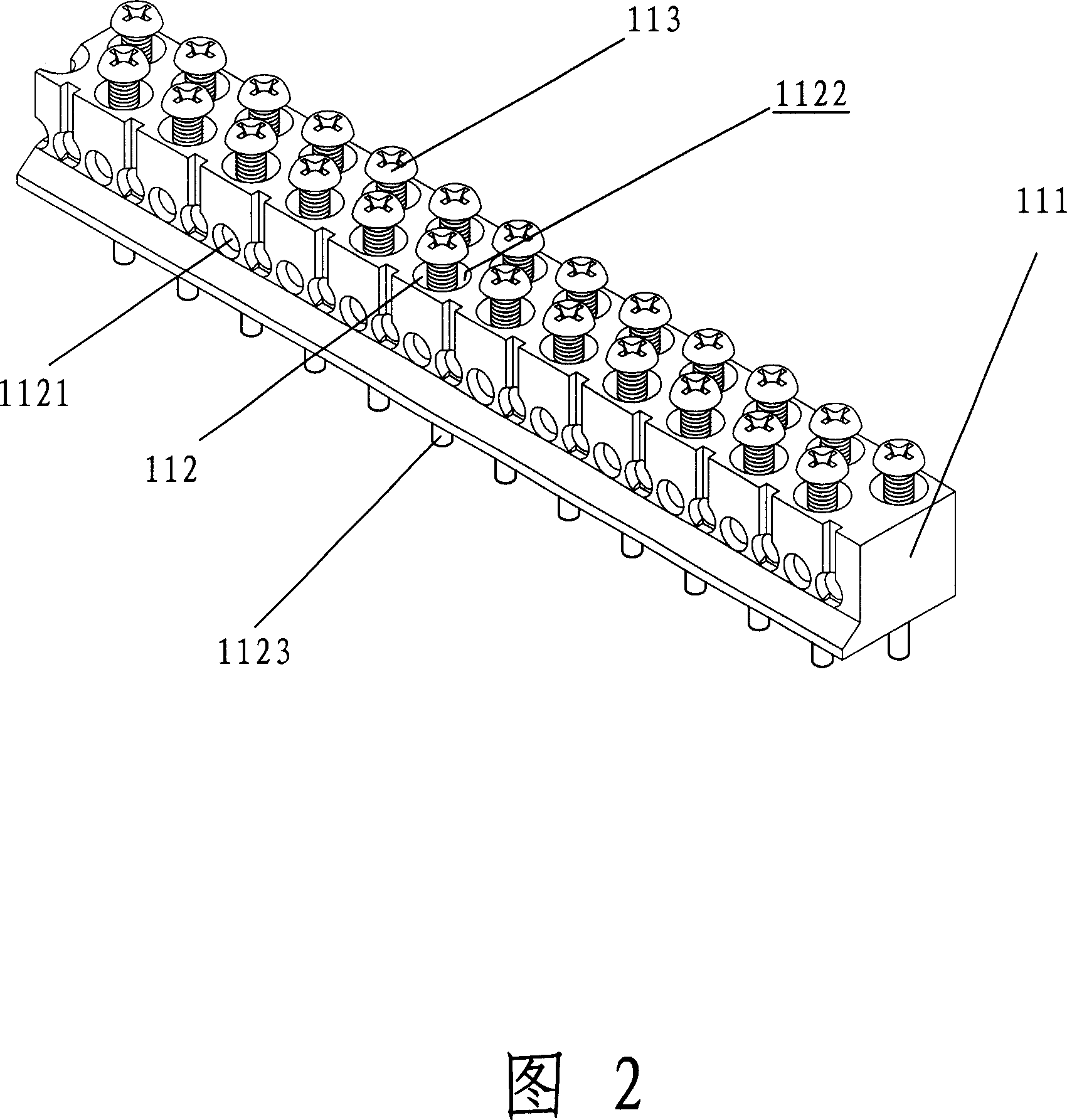
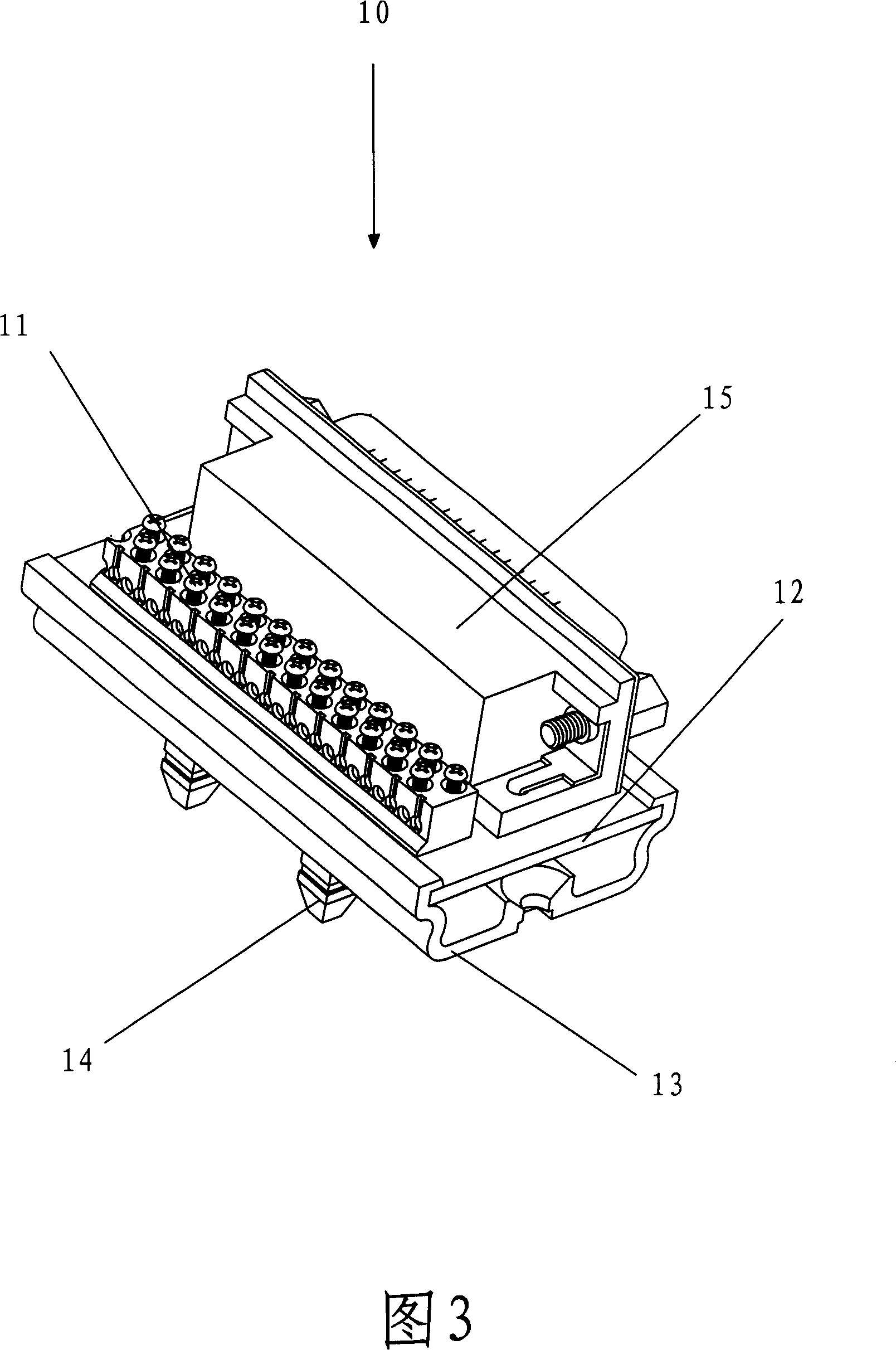
[0034] Specific embodiments of the present invention will now be described with reference to the drawings, in which like reference numerals represent like elements. First please refer to FIG. 1 and FIG. 3 , the crimping type component board 10 of the present invention includes components 15 , wiring bars 11 , printed circuit board 12 , board base 13 and mounting feet 14 .

[0035] The components 15 are generally weak current components and embedded unit circuits that can be directly installed on the circuit board, such as triodes, thyristors, integrated circuits, variable resistors, variable capacitors, input and output interfaces and various system cards The components 15 are generally soldered on the predetermined printed circuit board 12 and electrically connected to the circuit on the printed circuit board 12 .

[0036] The printed circuit board 12 is generally an epoxy resin printed circuit board. The circuit design and specification design are carried out according to th...


PUM


Abstract

A press-joint element board is prepared for erecting said element on printed circuit board arranging insulated shell and a numbers of wiring terminals embedded in said shell on wiring bus, setting said wiring bus on printed circuit board, connecting said wiring terminals to element, containing said printed circuit board in board base and setting erection foot on said board base.

Description

technical field [0001] The invention relates to an electronic circuit experiment equipment, in particular to a crimping component board and a method for connecting it to the experiment board. Background technique [0002] Electronic research institutes, schools and electronic companies often do electronic circuit experiments in electronic product development experiments and tests. With the popularization of electronic science and technology, hundreds of millions of electronic enthusiasts often do various electronic circuit experiments by themselves. . When doing electronic circuit experiments, it is necessary to connect electronic components (transistors, thyristors, integrated circuits, etc.) and electronic devices (variable resistors, variable capacitors, input and output interfaces, system card sockets, etc.) experiment. [0003] For a long time, two methods of plugging and welding are usually used in experiments to connect electronic components to the experiment board....

Claims


Application Information

Patent Timeline
IPC IPC(8): G09B23/18H05K1/18H05K7/02H05K13/04H01R9/22H01R4/30
Inventor 黎荣昌
Owner 黎荣昌
Features
  • R&D
  • Intellectual Property
  • Life Sciences
  • Materials
  • Tech Scout
  • Unparalleled Data Quality
  • Higher Quality Content
  • 60% Fewer Hallucinations
Learn More