
New type direct methanol fuel cell

A methanol fuel cell, direct technology, applied to fuel cells, fuel cell components, circuits, etc., can solve the problems of methanol leakage, electrode activity reduction, methanol fuel loss, etc. The effect of simplifying battery structure and improving performance

Inactive Publication Date: 2007-12-26
NANTONG UNIVERSITY
View PDF0 Cites 7 Cited by
  • Summary
  • Abstract
  • Description
  • Claims
  • Application Information

AI Technical Summary

Problems solved by technology

At present, the development of direct methanol fuel cells faces two key problems: one is that the solid electrolyte membrane widely used in direct methanol fuel cells is the Nafion membrane originally designed for hydrogen-oxygen proton exchange membrane fuel cells, which is expensive and has obvious Methanol leakage (crossover) phenomenon, methanol directly penetrates the Nafion membrane and is lost, resulting in a large loss of methanol fuel and a decrease in the power density of DMFC. At the same time, methanol seeps to the cathode and reacts on the cathode, resulting in poisoning of the cathode catalyst and greatly shortening battery life. The second is that methanol oxidizes slowly on the surface of the anode, and carboxyl species such as CO that are strongly adsorbed on the surface of the anode are produced during the oxidation process, which poisons the electrode and reduces the activity of the electrode.
Although the leakage resistance to methanol has been greatly improved, the leakage problem of methanol has not been completely solved

Method used


Image

  • New type direct methanol fuel cell

Examples


Embodiment 1

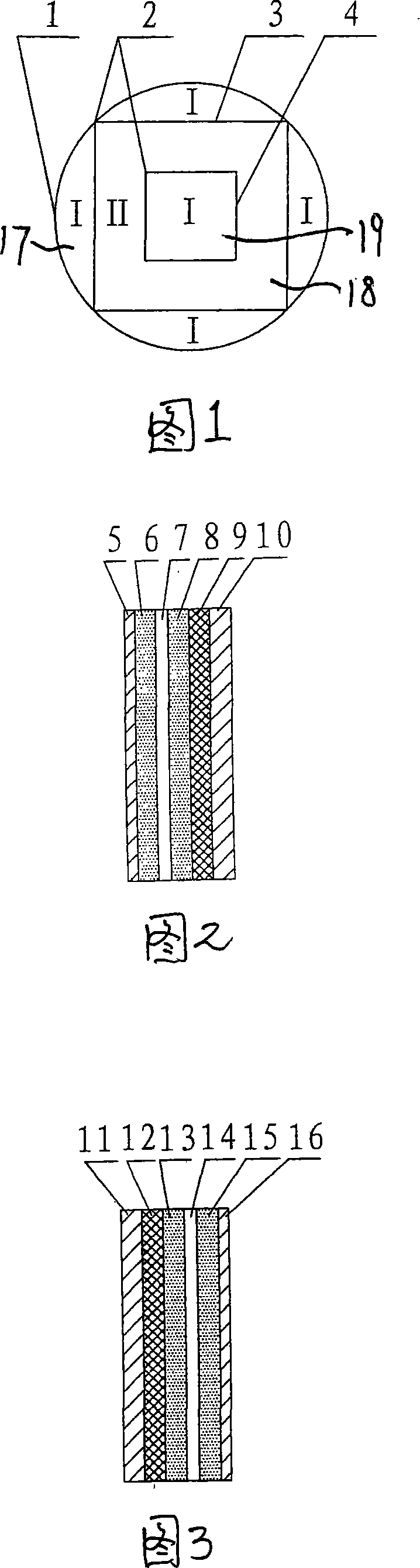
[0023] A new type of direct methanol fuel cell, comprising a battery casing 1, an external electrode 3 is arranged in the battery casing, the external electrode 3 is connected to the battery casing 1 through a welding point 2, and an air chamber 17 is arranged between the external electrode 3 and the battery casing 1, and The inner electrode 4 is arranged inside the electrode, the gel mobile phase chamber 18 is arranged between the inner electrode 4 and the outer electrode 3, and the air chamber 19 is arranged inside the inner electrode, wherein the gel mobile phase is made of the raw materials of the following weight components:

[0024] CH 3 OH 20%

[0025] h 2 SO 4 30%

[0026] h 2 O 20%

[0027] Heteroacids 3%

[0028] Conductive polymer and / or metal powder 5%

[0029] Metal organic compounds or metal salts 22%.

[0030] Metal-organic compounds are titanates (or silicates), and metal salts are sodium silicates. The heteroacid is perfluorosulf...

Embodiment 2

[0034] The weight ratio of each raw material in the gel mobile phase preparation is:

[0035] CH 3 OH 40%

[0036] h 2 SO 4 20%

[0037] h 2 O 20%

[0038] Heteroacids 5%

[0039] Conductive polymer 3%

[0040] Metal organic compounds or metal salts 12%. The conductive polymer is polyaniline (or polypyrrole).

[0041] All the other are with embodiment 1.

Embodiment 3

[0043] The weight ratio of each raw material in the gel mobile phase preparation is:

[0044] CH 3 OH 50%

[0045] h 2 SO 4 10%

[0046] h 2 O 10%

[0047] Heteroacids 10%

[0048] Conductive polymer 5%

[0049] Metal organic compound or metal salt 15%.

[0050] All the other are with embodiment 2.


PUM


Abstract

Without use of proton exchange membrane, the disclosed fuel battery includes shell of battery. Through welding point, the shell of battery is connected to outer electrode inside the shell. An air chamber is setup between the shell and the outer electrode. Inner electrode is setup at inner side of the outer electrode. Chamber of gel mobile phase is setup between inner electrode and outer electrode. An air chamber is setup at inner side of the inner electrode. Using gel mobile phase of possessing higher capability of conducting protons and electrons to replace solution mobile phase of liquid phase electrolyte of vitriol and methanol popular used currently, the invention solves issue of methanol leakage radically so as to lower poisoning cathode and anode catalyst of direct methanol fuel battery (DMFB). The invention raises performance of fuel battery, lowers manufacturing cost, and promotes progress of industrialization of DMFB.

Description

Technical field: [0001] The invention relates to a methanol-connected fuel cell. Background technique: [0002] Direct Methanol Fuel Cell (DMFC) has the advantages of low energy consumption, high energy density, abundant sources of methanol, low price, simple system, convenient operation, low noise, etc. Promising chemical power sources have attracted widespread attention. At present, the development of direct methanol fuel cells faces two key problems: one is that the solid electrolyte membrane widely used in direct methanol fuel cells is the Nafion membrane originally designed for hydrogen-oxygen proton exchange membrane fuel cells, which is expensive and has obvious Methanol leakage (crossover) phenomenon, methanol directly penetrates the Nafion membrane and is lost, resulting in a large loss of methanol fuel and a decrease in the power density of DMFC. At the same time, methanol seeps to the cathode and reacts on the cathode, resulting in poisoning of the cathode cataly...

Claims


Application Information

Patent Timeline
IPC IPC(8): H01M8/02H01M8/00H01M8/0232H01M8/1011
CPCY02E60/50Y02P70/50
Inventor 鞠剑峰黄明宇倪红军吴东辉华平
Owner NANTONG UNIVERSITY
Features
  • Generate Ideas
  • Intellectual Property
  • Life Sciences
  • Materials
  • Tech Scout
  • Unparalleled Data Quality
  • Higher Quality Content
  • 60% Fewer Hallucinations
Learn More