Torsion beam suspension

A technology of torsion beam type suspension and torsion beam, which is applied to suspensions, elastic suspensions, cantilevers mounted on pivots, etc., can solve the problem of narrow freedom in selecting the arrangement position of the threaded hole, increased processes, etc. Cost increase and other problems, to achieve the effect of improving rigidity, suppressing seat surface deformation, and eliminating thermal strain

Inactive Publication Date: 2007-12-26
F TECH INC
View PDF2 Cites 6 Cited by
  • Summary
  • Abstract
  • Description
  • Claims
  • Application Information

AI Technical Summary

Problems solved by technology

According to the above, since the main shaft support plate adopts a remarkably thick plate structure, when the product is to be provided by press punching, a large special press processing facility is required to cause a substantial cost increase, and when it is to be provided by hot forging When supplying products, the number of processes such as surface cutting increases, resulting in a significant cost increase
[0009] In addition, the present applicant proposes the following improvements in order to reduce the thickness of the main shaft support plate to achieve weight reduction while suppressing the occurrence of thermal strain associated with welding to solve the above problems (for example, refer to Japanese Patent Application No. 2002-199449 ), that is, the plate is fixed by fitting and welding the curved flange formed on the outer four corners of the main body of the main shaft support plate to the outer periphery of the rear end of the trailing arm. However, the rear half of the trailing arm is In the case of a pipe structure extending substantially linearly, the open end surface of the trailing arm is a cut surface obliquely intersecting with respect to the axis of the arm. Therefore, in the above-mentioned improvement, the curved flange cannot be aligned with the rear end of the trailing arm. Peripheral mosaicism, difficult to apply
In addition, in order to install the main shaft, etc., it is necessary to accommodate the four threaded hole portions dispersedly arranged in front, rear and up and down four positions of the main shaft axis with respect to the main shaft axis, all of which are accommodated inside the opening end surface of the rear end of the arm, which makes the threaded holes The choice degree of freedom of the arrangement position of the part is narrow

Method used


Image

  • Torsion beam suspension
  • Torsion beam suspension
  • Torsion beam suspension

Examples


Embodiment 1

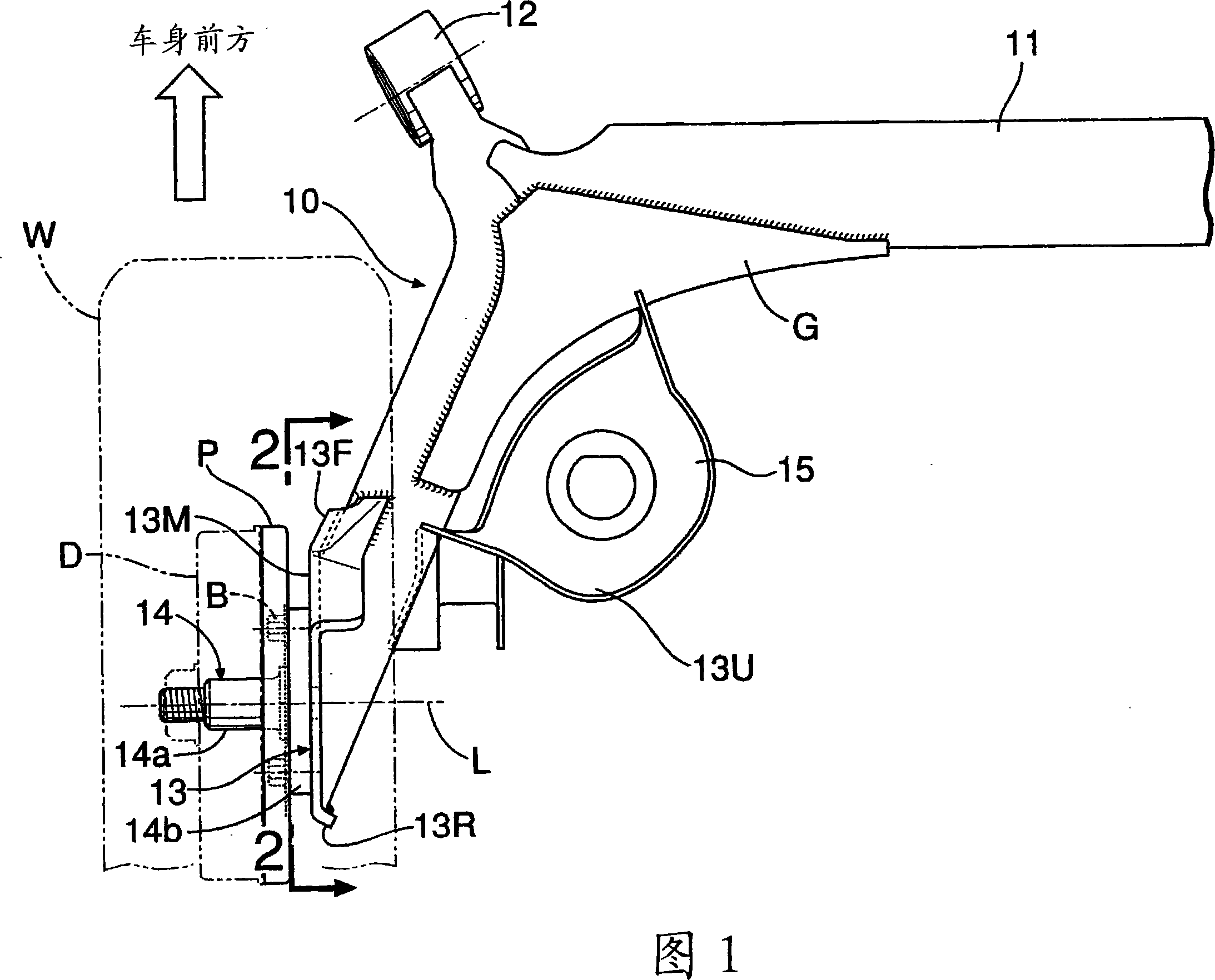
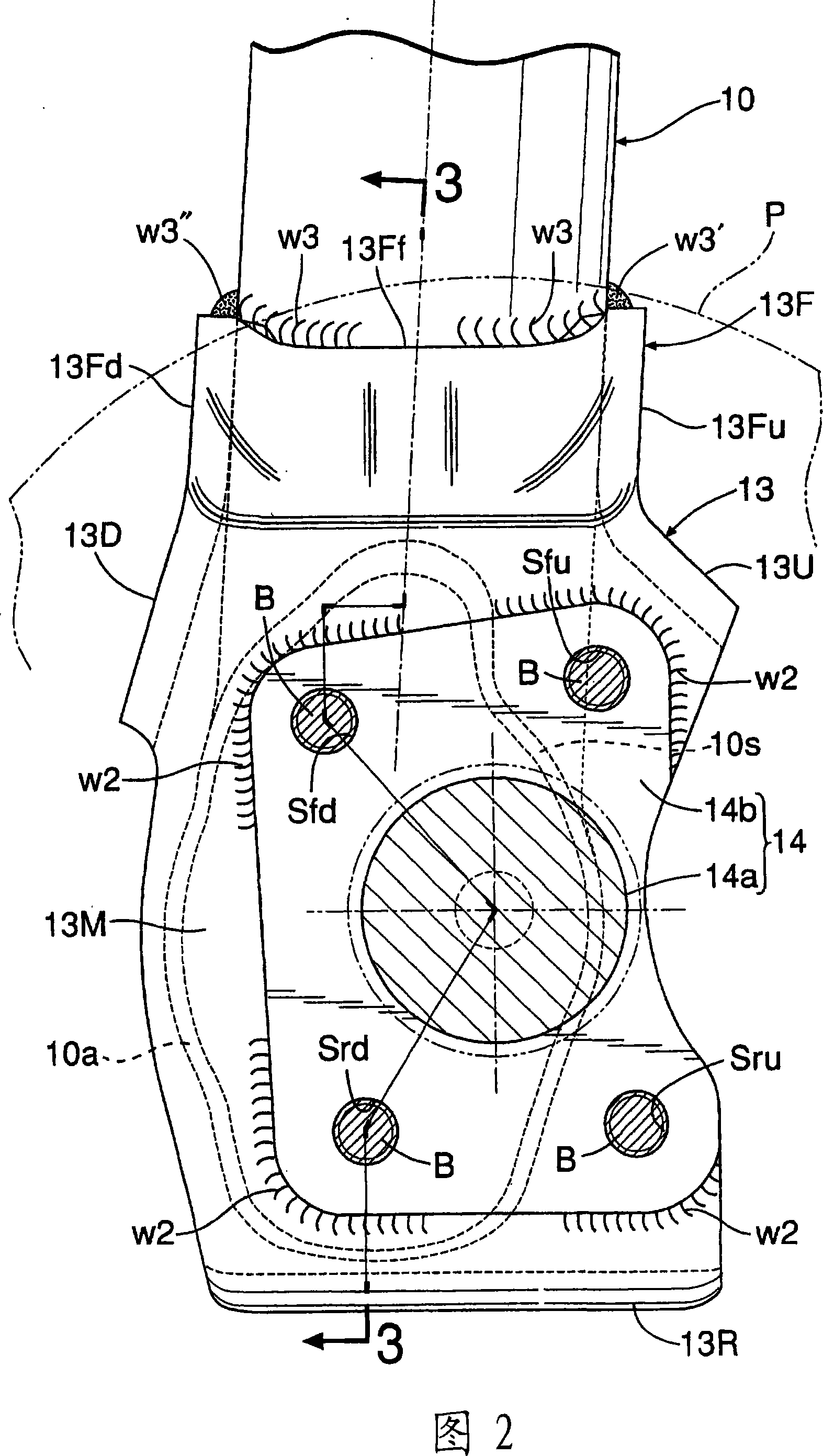
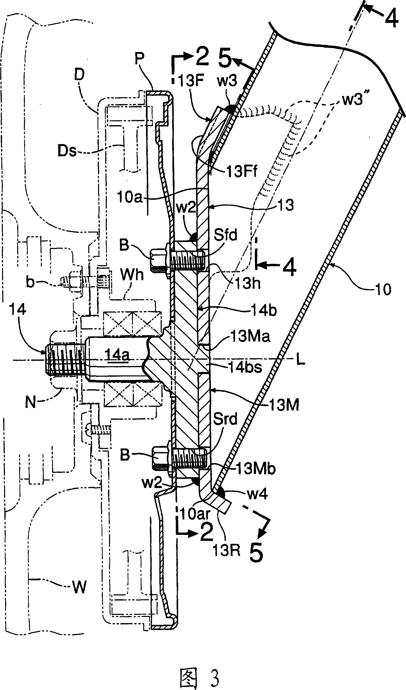
[0078] 1 to 5 show a first embodiment of the present invention.

[0079] First, FIG. 1 is a top view of the left half of the torsion beam suspension for the rear wheels of an automobile, and the right half has a left-right symmetrical structure with respect to the front and rear centerlines of the vehicle body. This torsion beam type suspension has: a pair of left and right trailing arms 10 extending substantially linearly in the substantially front-rear direction of the vehicle body; The torsion beam 11 is welded between the end of the torsion beam 11 and the middle of the trailing arm 10 to increase the bonding strength between them.

[0080] A cylindrical trailing arm support part 12 is welded on the front end of each trailing arm 10, and the trailing arm support part 12 passes through a rubber bush joint (not shown) accommodated in the trailing arm support part 12. It is pivotally supported on the vehicle body to swing freely up and down. The rear wheel W is freely rotat...

Embodiment 2

[0105] Next, a second embodiment of the present invention will be described with reference to FIGS. 8 to 12 . Since the basic structure of the torsion beam suspension in this second embodiment is the same as that in the first embodiment, the reference numbers of the corresponding components in the first embodiment are changed to 100 and assigned to the second embodiment Each constituent element of the basic structure, the description of the basic structure is omitted. Hereinafter, the parts different from those of the first embodiment will be mainly described.

[0106] The spindle support plate 113 has a substantially square-shaped plate main body 113M whose back surface is butted against the opening end surface 110 a at the rear end of the trailing arm 110 and welded w11 . The surface (the left side in FIG. 10 ) of the plate main body 113M is a flat mounting seat surface with respect to the main shaft 114, and on the back side of the main plate main body, the main shaft axis...


PUM


Abstract

Torsional beam type suspending rack is provided in the present invention. In the torsional beam type suspending rack making opening end face of towing arm and main shaft supporting plate butt welding, on the front end of the main shaft supporting plate (13) plate main body (13M), integrated connecting a front side bending flange (13F) extending along the back end external side of the towing arm (10) towards front and front end edge welding (W3) at the back end external side, and at the plate main body (13M) back end integrated connecting a rear side bending flange (13R) clamping and welding (4W) at the rear end edge of the towing arm (10). The main shaft substrate (14b) is overlapped and fixed (W2) on the external side of the plate main body (13M), and has four screw hole parts (Sfu, Sfd, Sru, Srd) at the front and back and un and down of the maid shaft axes separating the main shaft axes, the screw hole parts is used for combining the plate shape component (P) associated with the braking device and the bolt used for the main shaft substrate (14b), therefore, it can restrain effect of welding thermal strain, and can make the main shaft supporting plate thin-wall to realize light weight and lower cost.

Description

technical field [0001] The present invention relates to a torsion beam type suspension that connects left and right trailing arms that extend approximately in the front-rear direction of the vehicle body and swing up and down, and both ends of a torsion beam that extends approximately in the left-right direction of the vehicle body. The main shaft for pivotally supporting the wheels is fixed on the main shaft supporting plate welded to the left and right trailing arms. Background technique [0002] This torsion beam type suspension is conventionally known, for example, as described in the following patent document 1. In the torsion beam type suspension, since the trailing arm is made into a hollow tube shape, the cross section can be obtained using relatively low-cost production equipment. Efficient closed-section arm construction. [0003] However, in this known torsion beam suspension, in order to separate the weld joint from the spindle mounting surface to reduce the inf...

Claims


Application Information

Patent Timeline
Patent Type & Authority Applications(China)
IPC IPC(8): B60G9/04
CPCB60G2206/8201B60G7/008B60G2206/20B60G21/051B60G2206/50
Inventor 井上满菊地文雄
Owner F TECH INC
Why Eureka
Try Eureka