Air conditioner residual heat utilization device

A waste heat and air conditioning technology, applied in air conditioning systems, space heating and ventilation, applications, etc., can solve the problem of low waste heat utilization efficiency, and achieve the effect of improving waste heat utilization efficiency

Inactive Publication Date: 2008-01-02
上海市复旦中学
View PDF1 Cites 4 Cited by
  • Summary
  • Abstract
  • Description
  • Claims
  • Application Information

AI Technical Summary

Problems solved by technology

Since the refrigerant during cooling in the patented device releases heat from the heat exchanger A (outdoor heat exchanger 30) in advance and then heats up the heat

Method used


Image

  • Air conditioner residual heat utilization device
  • Air conditioner residual heat utilization device

Examples


Embodiment Construction

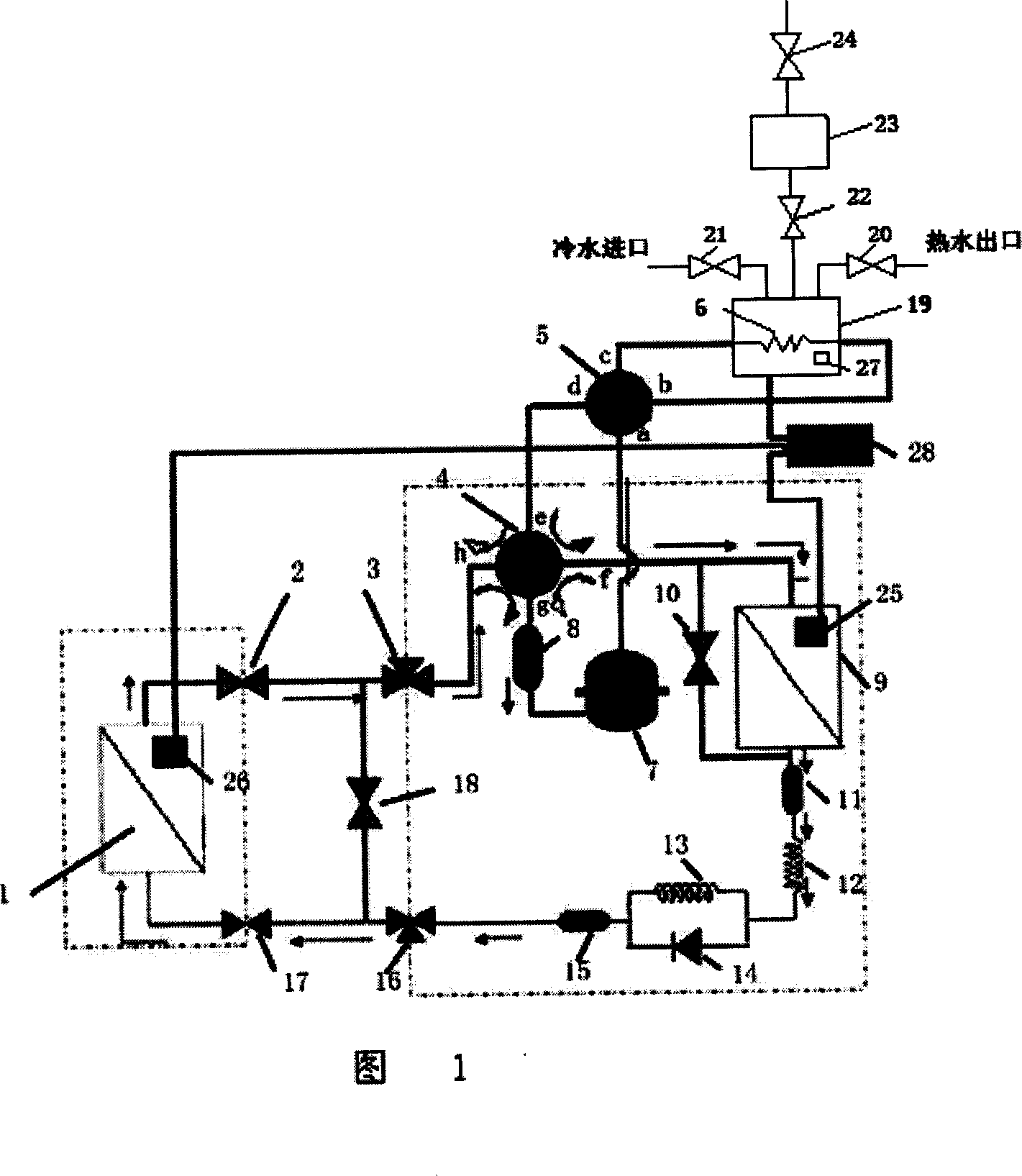
[0028] The technical solution of the present invention will be further described below in conjunction with the description of the accompanying drawings and specific embodiments:

[0029] As shown in Figure 1, when the system is operating in cooling mode, the indoor heat exchanger 1 becomes an evaporator, and the outdoor heat exchanger 9 becomes a condenser. The refrigerant first absorbs heat indoors, and the low-temperature and low-pressure superheated gas from the indoor heat exchanger 1 enters the gas-liquid separator 8 to separate the liquid through the solenoid valve 2, low-pressure valve 3, and four-way valve 4 inlet port h (outlet port g). Finally, the dry superheated gas is inhaled by the compressor 7 and compressed to become high-temperature and high-pressure gas to be discharged. When the water temperature is low, the gas enters the additional heat exchanger through the inlet port a of the additional four-way valve 5. Since the additional heat exchanger 6 is placed in ...


PUM


Abstract

The invention discloses an air conditioner surplus heat utilizing device, which is characterized by the following: connecting outlet end of compressor to the one inlet end of additive four-way valve; cascading the relative outlet end with the additive heat exchanger; connecting to the other inlet end of the additive four-way valve; connecting the inlet end of the four-way valve to the relative outlet end; arranging a temperature sensor on the additive heat exchanger; connecting to controller; arranging the additive heat exchanger in main water tank; arranging an additive four-way valve; connecting the additive four-way to the additive heat exchanger; heating the water in the main water tank through the additive heat exchanger; increasing availability of the surplus heat.

Description

technical field [0001] The invention relates to a device for utilizing waste heat of an air conditioner, in particular to a device for heating hot water by using the waste heat of an air conditioner. Background technique [0002] At present, known air conditioners absorb indoor heat energy during cooling to lower the temperature, and at the same time discharge a large amount of heat to the outside. This heat is not fully utilized and is discharged into the environment, which is not conducive to environmental protection and energy saving. Patent No. CN00229050.2 discloses a technical scheme of "air conditioner with heat pump water heater", which discloses: as shown in Figure 2, after the refrigerant absorbs heat in the heat exchanger C (that is, the indoor heat exchanger 29) After being compressed by the compressor, the heat is released through the heat exchanger A (that is, the outdoor heat exchanger 30), and the heat is discharged to the air outdoors, and then enters the he...

Claims


Application Information

Patent Timeline
IPC IPC(8): F25B1/00F24F5/00F24H4/04
CPCY02B30/123Y02B30/12
Inventor 周顺
Owner 上海市复旦中学
Why Eureka
Try Eureka