Bevel-gear right-angle milling head

A bevel gear and milling head technology, applied in metal processing mechanical parts, driving devices, metal processing equipment, etc., can solve the problems of low processing accuracy, low production efficiency, low precision, etc., and achieve convenient and accurate installation, high production efficiency, The effect of high machining accuracy

Inactive Publication Date: 2008-01-09
SHANGHAI BLOWER WORKS
View PDF0 Cites 37 Cited by
  • Summary
  • Abstract
  • Description
  • Claims
  • Application Information

AI Technical Summary

Problems solved by technology

However, because the milling cutter and the milling machine spindle are in the same direction in the prior art, the milling cutter is perpendicular to the processing surface during milling, so the end face parallel to the milling machine spindle cannot be processed, especially for inner surface processing such as holes.
Generally, slotting machines are used to process inner surfaces such as holes, that is, vertical planer, but the processing method is reciprocating motion, large inertia, low speed, single processing, low precision, large deviation range, rough surface, especially for The processing of keyways in large shaft holes that require high precision, such as the processing of keyways in the inner holes of impellers with a diameter of more than 2 meters and an impeller weighing more than 4 tons, cannot be processed by slotting machines for super large and overweight workpieces, and its production efficiency is low. Low precision, can no longer meet the processing requirements

Method used


Image

  • Bevel-gear right-angle milling head
  • Bevel-gear right-angle milling head

Examples


Embodiment Construction

[0015] The present invention will be further described below in conjunction with the accompanying drawings and specific embodiments.

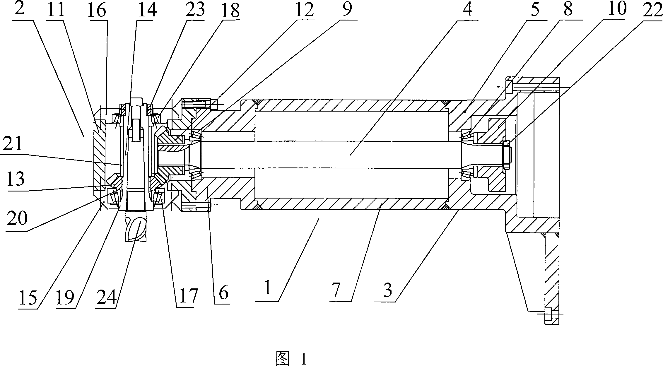
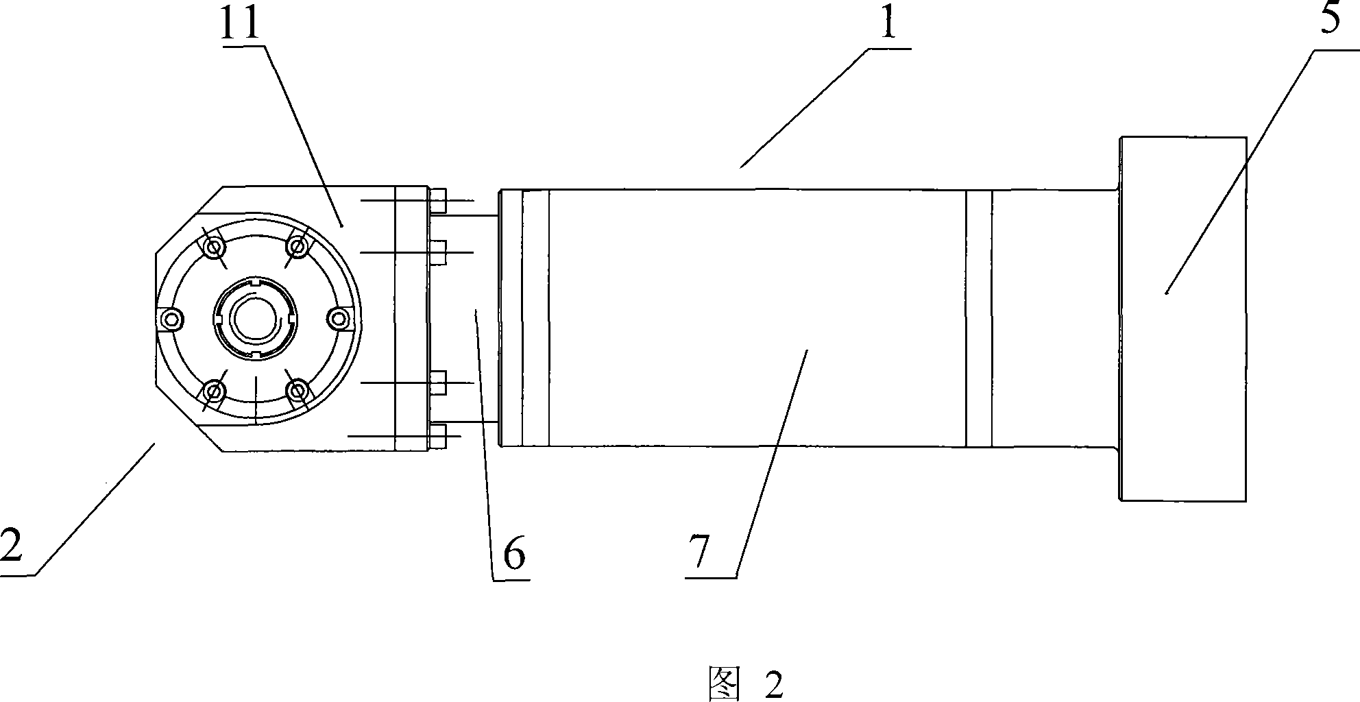
[0016] A bevel gear right-angle milling head includes a transmission device 1 and a steering device 2, wherein the transmission device 1 includes a milling head base 3 and a connecting shaft 4. The milling head base 3 comprises the end 5 of the milling head base, the head end 6 of the milling head base, and the round pipe 7 welded between the two 5,6, and the end 5 of the milling head base is affixed to the milling machine. The milling head base 3 is segmented, which facilitates the processing and manufacturing of the milling head base 3 . The end 5 of the milling head base is provided with a first bearing 8, the head end 6 of the milling head base is provided with a second bearing 9, the connecting shaft 4 is arranged in the first bearing 8 and the second bearing 9, the first bearing 8 and the second Bearings 9 are all single row tapered roll...


PUM


Abstract

The present invention relates to machining fixture, and is especially one kind of milling head for holding milling cutter in numerically controlled machine tool. The rectangular bevel gear milling head includes one driving mechanism and one steering mechanism. The driving mechanism includes one milling head base fixed onto the milling machine and one connecting shaft set inside the base and connected to the milling machine spindle. The steering mechanism includes one milling head casing, two bevel gears to constitute one rectangular gear train, and one milling head spindle. The milling head has capacity of altering the milling cutter rotation direction, capacity of machining inner surface of hole or end parallel to the milling machine spindle, high production efficiency and high machining precision.

Description

technical field [0001] The invention relates to a machining fixture, in particular to a milling head used for installing a milling cutter in a numerical control machine tool. Background technique [0002] Milling machines play an important role in the machining of parts. They have high production efficiency and high machining accuracy. They are usually used for machining planes, outer end grooves, tooth shapes, etc. However, because the milling cutter and the milling machine spindle are in the same direction in the prior art, the milling cutter is perpendicular to the processing surface during milling, so the end face parallel to the milling machine spindle cannot be processed, especially for inner surface processing such as holes. Generally, slotting machines are used to process inner surfaces such as holes, that is, vertical planer, but the processing method is reciprocating motion, large inertia, low speed, single processing, low precision, large deviation range, rough su...

Claims


Application Information

Patent Timeline
Patent Type & Authority Applications(China)
IPC IPC(8): B23Q5/04
Inventor 余化龙方茂森钱敏龙
Owner SHANGHAI BLOWER WORKS
Why Eureka
Try Eureka