Finger joint for robot clever hand finger

A dexterous hand and robot technology, applied in the directions of manipulators, chucks, manufacturing tools, etc., can solve the problems of long transmission force space distance, drive system lag, poor position accuracy, etc., to reduce maintenance difficulty, high integration, and reduce maintenance. cost effect

Inactive Publication Date: 2008-01-09
HARBIN INST OF TECH
View PDF0 Cites 18 Cited by
  • Summary
  • Abstract
  • Description
  • Claims
  • Application Information

AI Technical Summary

Problems solved by technology

[0003] In order to solve the problems of poor reliability of the finger joints of the existing robot dexterous hand, lagging performance of the drive system, poor positional accuracy, complex structure, poor maintainability, and long space distance for transmitting force, the present invention further provides a robot dexterous hand fingers

Method used


Image

  • Finger joint for robot clever hand finger
  • Finger joint for robot clever hand finger
  • Finger joint for robot clever hand finger

Examples


specific Embodiment approach 1

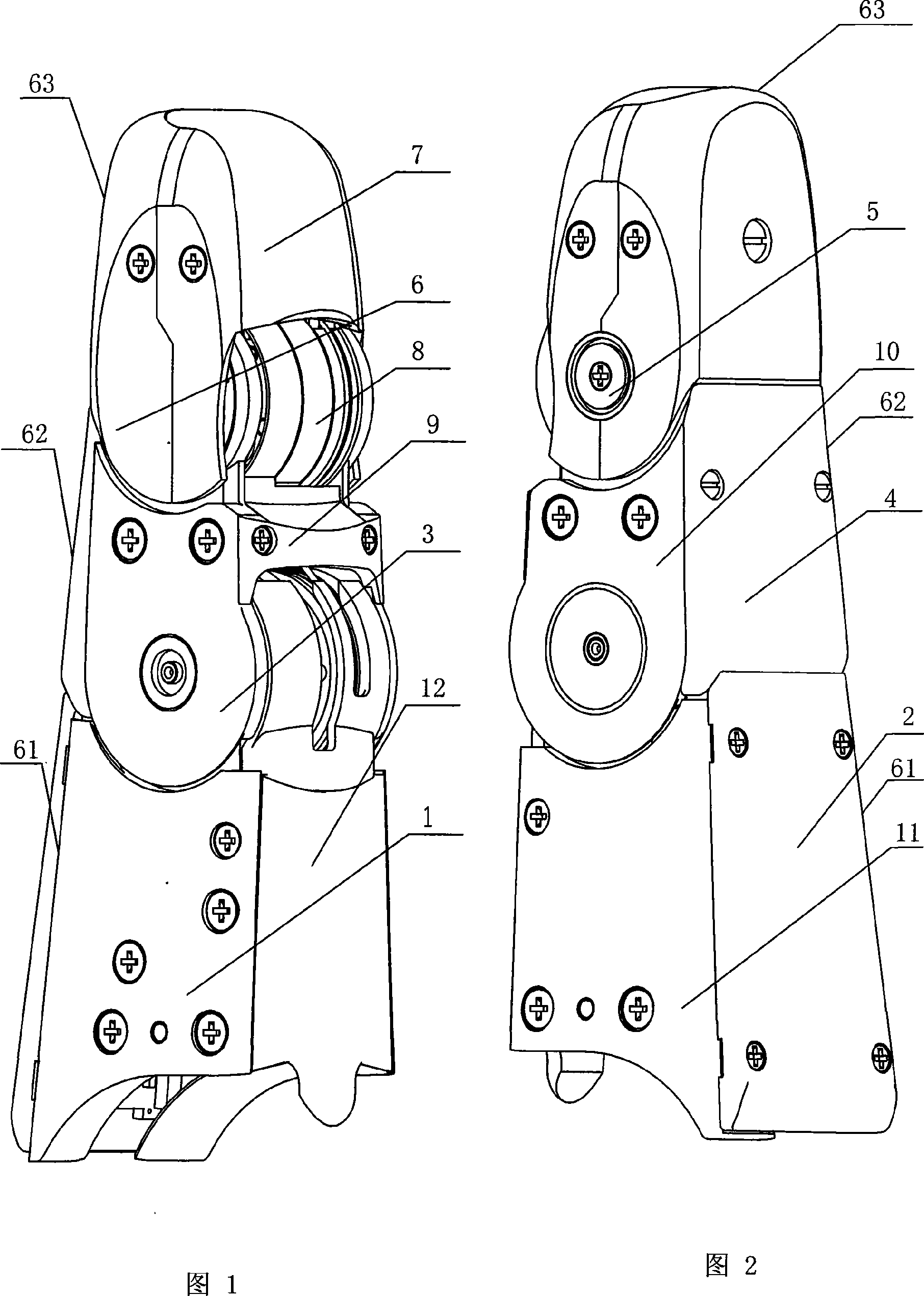
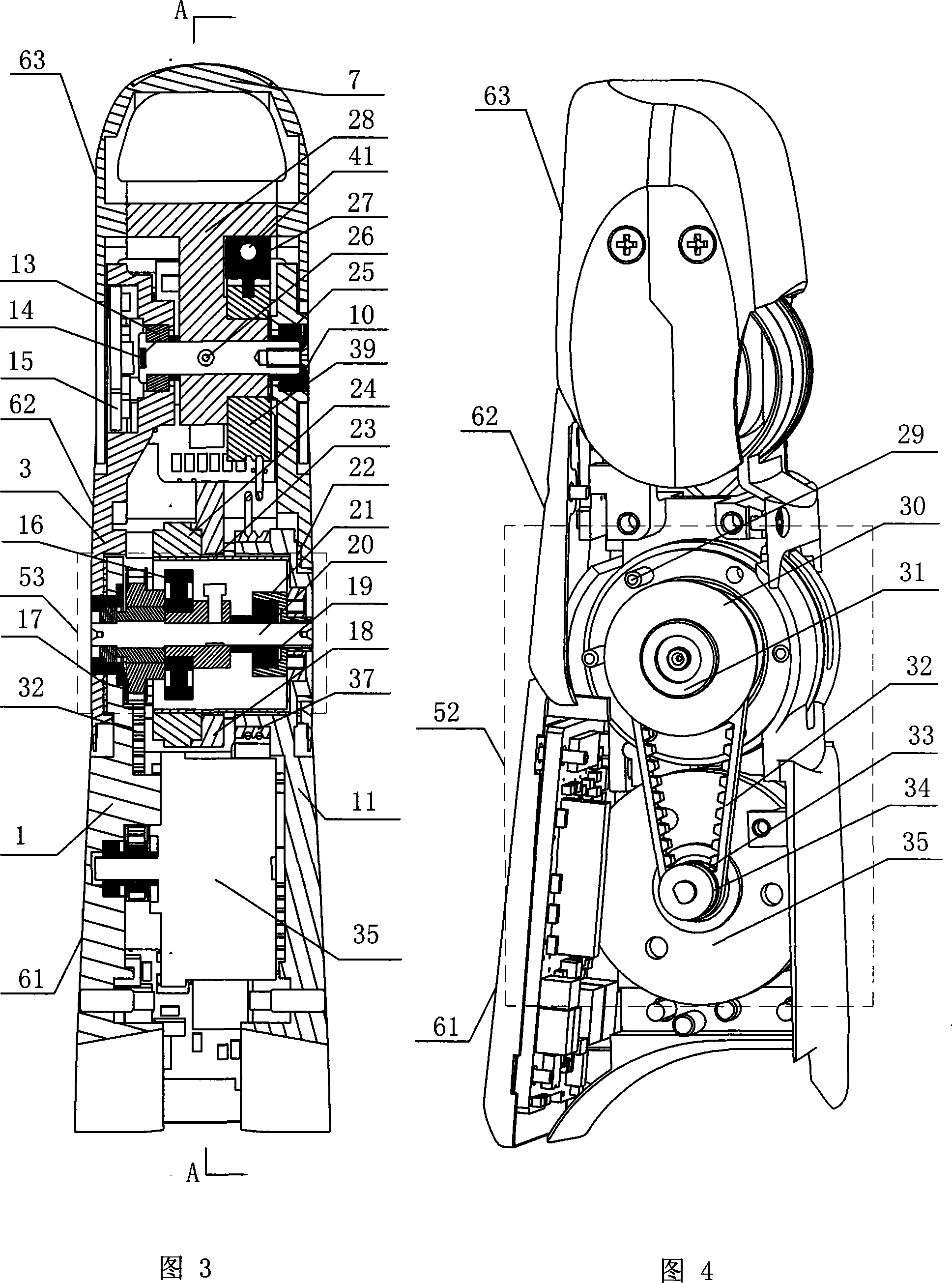
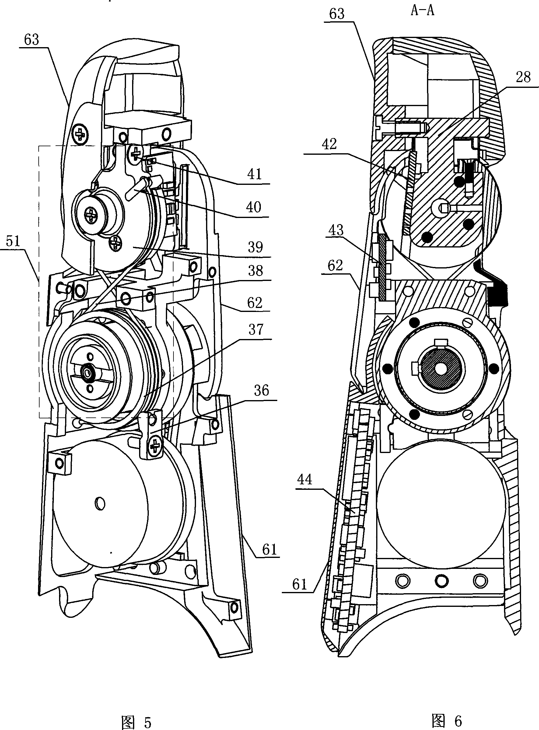
[0007] Embodiment 1: As shown in FIGS. 1 to 3 , the finger joints of the fingers of the robotic dexterous hand in this embodiment consist of a first knuckle shell 61 , a second knuckle shell 62 , an end knuckle shell 63 , and a first joint shaft 20 , second joint shaft 26, motor 35, fingertip one-dimensional torque sensor 28, steel wire coupling transmission mechanism 51, belt transmission mechanism 52, harmonic speed reducer 53, transmission member 18; The lower end of the two-knuckle housing 62 is rotationally connected through the first joint shaft 20, and the upper end of the second knuckle housing 62 is rotationally connected with the lower end of the terminal knuckle housing 63 through the second joint shaft 26; the motor 35 is fixed on the first On the first knuckle left side plate 1 of the knuckle housing 61, the first synchronous pulley 34 in the belt transmission mechanism 52 is fixed on the output shaft of the motor 35, and the second synchronous pulley 31 in the bel...

specific Embodiment approach 2

[0009] Specific embodiment two: as shown in Figure 1 and Figure 2, the first knuckle shell 61 described in this embodiment consists of the first knuckle left side plate 1, the first knuckle right side plate 11, the first knuckle finger The belly cover 12 and the first knuckle upper cover 2 are composed, the left side of the first knuckle finger belly cover 12 and the left side of the first knuckle upper cover 2 pass through the first knuckle The left side plate 1 is fixedly connected; the right side of the first knuckle cover plate 12 is fixedly connected with the right side of the first knuckle upper cover plate 2 through the first knuckle right side plate 11 . The stable connection of the first phalanx can be realized, and the drive motor 35 and the circuit board 44 can be enclosed inside the phalanx without being exposed outside. Other compositions and connections are the same as in the first embodiment.

specific Embodiment approach 3

[0010] Specific embodiment three: as shown in Figure 1 and Figure 2, the second knuckle shell 62 described in this embodiment consists of the second knuckle left side plate 3, the second knuckle right side plate 10, the second knuckle finger Belly cover 9 and second knuckle upper cover 4, the left side of the second knuckle finger belly cover 9 and the left side of the second knuckle upper cover 4 pass through the left side of the second knuckle The side plate 3 is fixedly connected; the right side of the second knuckle cover plate 9 is fixedly connected with the right side of the second knuckle upper cover plate 4 through the second knuckle right side plate 10 . With such a structure, a stable connection of the first phalanx can be realized, and other components and connection relations are the same as those in the second embodiment.


PUM


Abstract

The present invention relates to finger joint of robot, and is especially finger joint of skillful robot hand. The present invention has one motor fixed to the inner wall of the first finger knuckle casing, the first synchronous pulley fixed onto the output shaft of the motor, the second synchronous pulley fixed onto the first joint shaft, one harmonic reducer mounted onto the first joint shaft, one driving member mounted onto the harmonic reducer, one 1D finger tip torque sensor mounted onto the second joint shaft, one first joint wire wheel connected to the inner wall of the first finger knuckle casing, and one second joint wire wheel connected to the 1D finger tip torque sensor. The finger joint of skillful robot hand has the advantages of high integration level, high reliability, high position accuracy and less hysteresis.

Description

technical field [0001] The invention relates to a finger joint of a robot finger. Background technique [0002] As an important branch of robot technology, robot dexterous hand technology has achieved good results after decades of development, and some representative dexterous hands have been born one after another, such as Stanford / JPL hand, Utan / M.I.T hand, DLR hand, NASA hand, etc. Some advances are mainly reflected in mechanical structure, drive, sensing, integration and control. However, due to the limitations of motor technology and electronic product manufacturing technology, the integration of previous dexterous hands has not reached a satisfactory level, such as Stanford / JPL hands, Utan / M.I.T hands, and commercialized Shadow hands. The driver is placed outside the dexterous hand (such as in the forearm), and the space for transmitting force is long and the path is irregular. These dexterous hands realize the transmission through tendons (ropes). The advantages of...

Claims


Application Information

Patent Timeline
Patent Type & Authority Applications(China)
IPC IPC(8): B25J17/00B25J15/00
Inventor 刘伊威刘宏樊绍巍金明河赵京东
Owner HARBIN INST OF TECH
Why Eureka
Try Eureka