Damping structure and composite material

A technology of damping composite materials and damping structures, which is applied to springs, springs, springs/shock absorbers made of plastic materials, etc., can solve the problems of inability to achieve vibration and noise reduction effects, and achieve obvious vibration and noise reduction effects. Reduce the intensity of vibration or sound, the effect of strong applicability

Active Publication Date: 2008-01-09
QINGDAO CREATE ENVIRONMENT CONTROL TECH
View PDF2 Cites 7 Cited by
  • Summary
  • Abstract
  • Description
  • Claims
  • Application Information

AI Technical Summary

Problems solved by technology

In the same way, if a general vibration-prone component adopts a constrained damping structure in which the constrained plate is basically a plane, it is also limited by the surface area of ​​the component and cannot achieve the ideal vibration and noise reduction effect.

Method used


Image

  • Damping structure and composite material
  • Damping structure and composite material
  • Damping structure and composite material

Examples


Embodiment 1

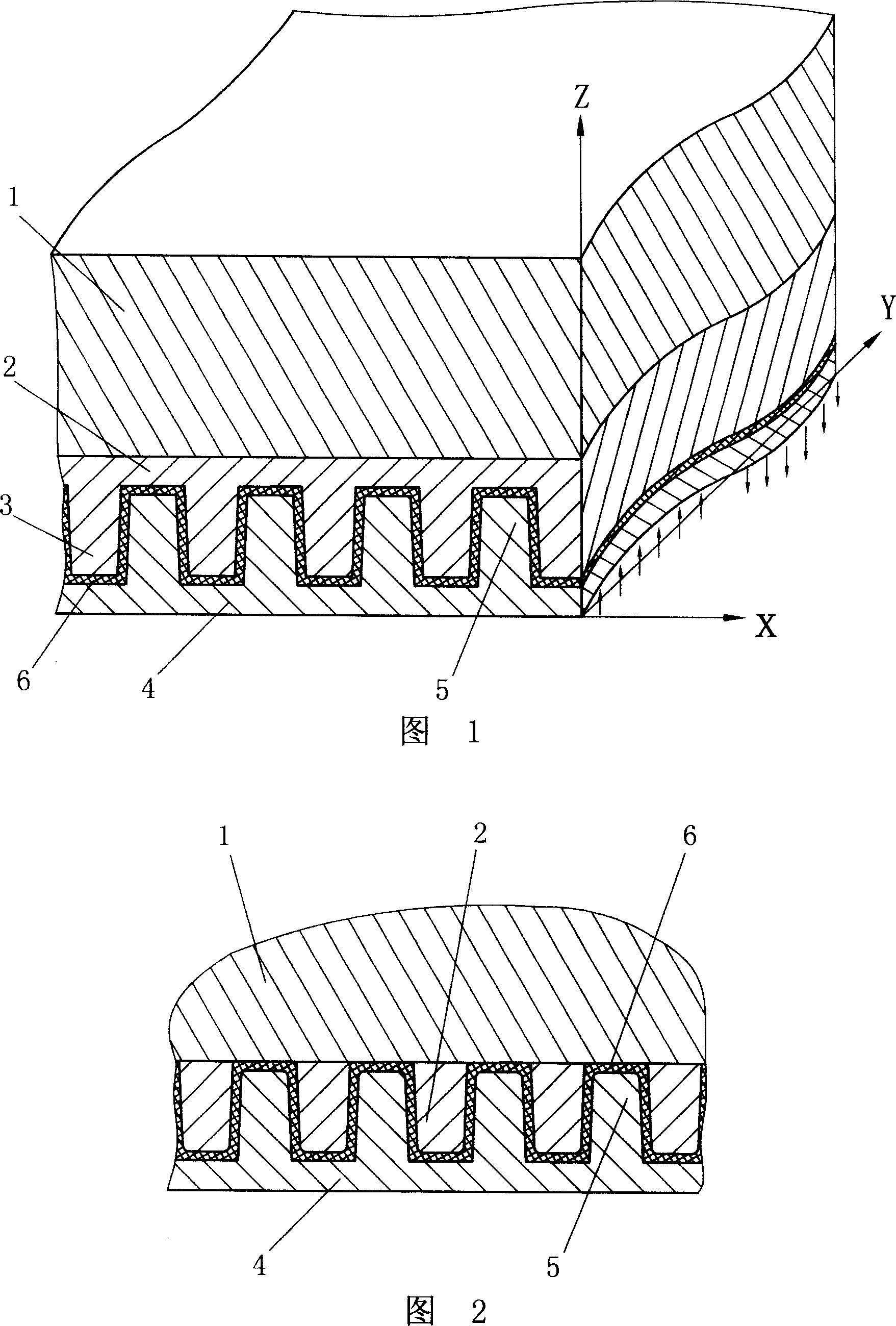
[0033] As shown in Figure 1, the component body 1 is a plate-shaped easy-to-vibrate casing of the machine, its main vibration shape is bending vibration, and the bending axis is the X axis. The connecting body 2 is fixed on the component body 1 with an adhesive, Protruding ribs 3 are provided at intervals on the connecting body 2, and the protruding ribs 3 cooperate with the protruding ribs 5 on the constraining body 4. The extending direction of the protruding ribs is the direction of the Y axis (perpendicular to the direction of the X axis). A continuous damping layer 6 is arranged between the connecting body 2 and the inner surface of the constraining body 4, and the material of the damping layer is vulcanized high-damping rubber. The above structures can be arranged continuously or at intervals on the surface of the component body.

[0034] When the component body is excited to vibrate, it bends and deforms around the X-axis. At this time, the damping material is forced to...

Embodiment 2

[0039] As shown in Figure 2, the difference from Embodiment 1 is that the connecting body 2 is simplified into a plurality of independent ribs, which are welded and fixed at intervals on the surface of the component body 1 and interlaced with the ribs 5 on the constraining body 4 Cooperate. At this time, a damping layer 6 is set between the outer surface of the component body 1 and the connecting body 2 and the inner surface of the constraint body 4, and a solid damping material, high-damping polyurethane is set in the damping layer, and the order of implementation is to mix the two-component damping materials well. Finally, paint it on the concave-convex surface of the constraining body, then press the constraining plate and the component, and the damping material is cured to form a damping layer.

Embodiment 3

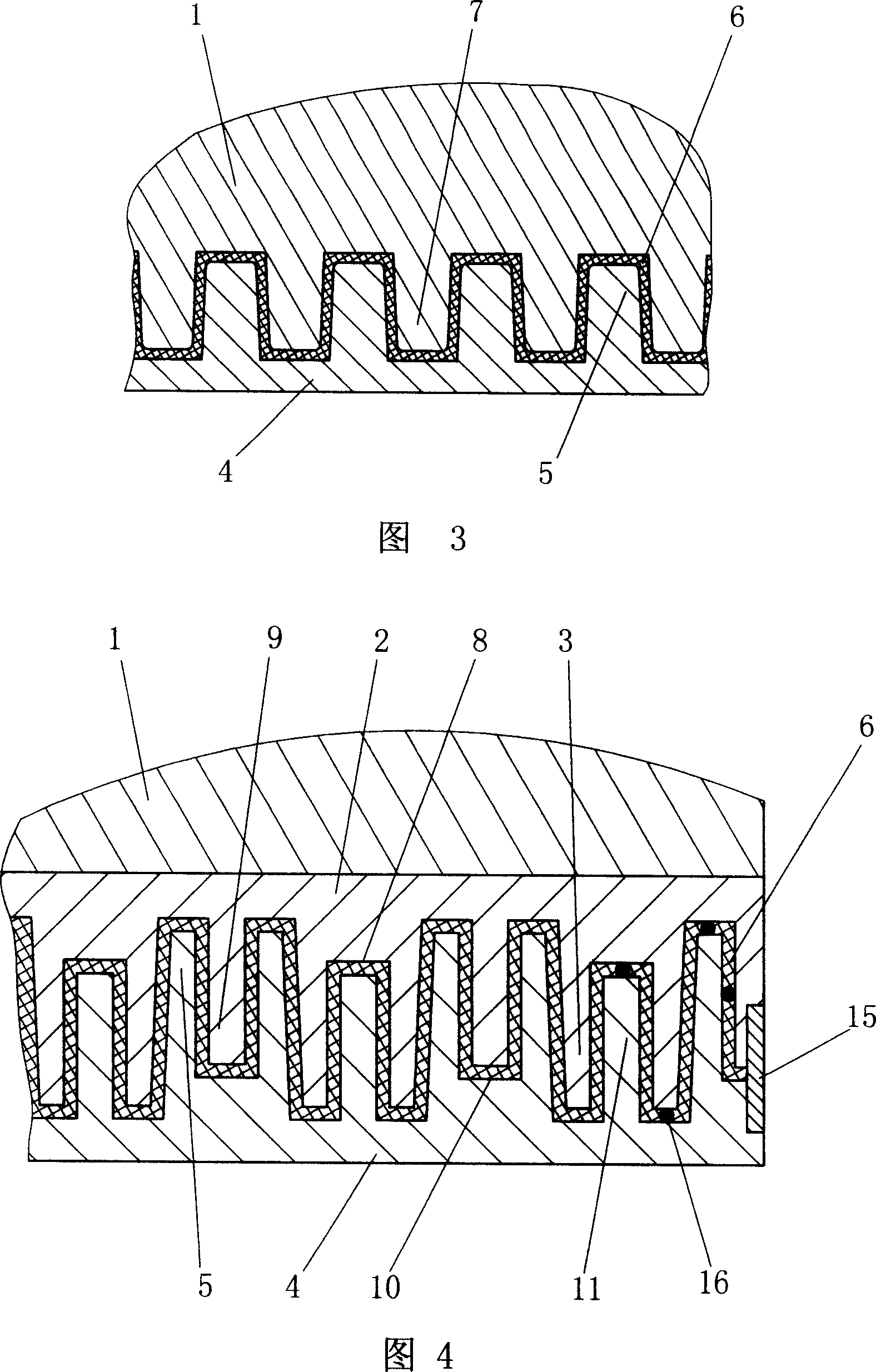
[0041] As shown in FIG. 3 , as an extension of the structure described in Example 1, for the component body 1 integrally cast with ribs 7 on its surface, the ribs 7 on its surface can be regarded as connectors. The ribs 7 on the surface of the component body cooperate with the ribs 5 on the constraining body 4. At this time, a damping layer 6 is set between the surface of the component body and the inner surface of the constraining body, and a solid damping material modified damping asphalt is set in the damping layer.

[0042] When the component 1 or the constraint body 4 is made of metal material, the connecting ribs on its surface can be formed by casting, machining or forging; when the component 1 or the constraint body 4 is made of aluminum, aluminum-magnesium alloy, or thermoplastic material, the rib Extrusion molding or injection molding can be used; when the member 1 or the constraint body 4 is a concrete structure, the ribs can be poured. For example, when the compone...


PUM


Abstract

This invention relates to vibration and noise control field, especially structure which can increase common component self damping and composite material using this structure. The component surface is continuously or alternately fixed with connector with concavo convex structure. The connector and binding body with corresponding concavo convex structure are cooperated. There is damping material between connector and binding body. This invention greatly increases the contacted and working area between damping material and component as well as binding body. It also increases applied moment the damping action applied on component bend neutral plane and bend axes. Thus, this invention can increase structural damping of components.

Description

technical field [0001] The invention relates to the field of vibration and noise control, in particular to a structure that increases the damping of common components and a composite material using the structure. Background technique [0002] The impact and harm of vibration are almost everywhere. Vibration damages buildings and affects the operation of precision instruments and equipment. Vibration and the noise it excites can also endanger human health. Thin-walled components on vehicles, machines, and electrical appliances, such as wheels, shells, boxes, and decks, are particularly prone to vibration, and will vibrate under the action of machine rotation, impact, and air flow. Vibration also produces noise; thin-walled components, long-span components, and super-long components on bridges, buildings, and engineering structures will vibrate substantially under the excitation of wind loads, human loads, traffic loads, and earthquake loads. System becomes easy to vibrate me...

Claims


Application Information

Patent Timeline
Patent Type & Authority Applications(China)
IPC IPC(8): F16F15/00B32B5/00
CPCF16F1/371F16F1/44
Inventor 尹学军
Owner QINGDAO CREATE ENVIRONMENT CONTROL TECH
Why Eureka
Try Eureka