
Polarization maintaining fiber apodization grating production method

A manufacturing method and technology of polarization-maintaining fibers, which are applied in cladding fibers, optical waveguides, lasers, etc., can solve the problems of low grating side lobe suppression ratio, limited measurement range, accuracy, and detection sensitivity of peripheral measuring equipment, etc. Screening single, conducive to multiplexing, stable and reliable use

Inactive Publication Date: 2008-01-09
西安盛佳光电有限公司
View PDF0 Cites 6 Cited by
  • Summary
  • Abstract
  • Description
  • Claims
  • Application Information

AI Technical Summary

Problems solved by technology

Although there are many methods for fabricating the existing fiber apodized grating, the sidelobe suppression ratio of the fabricated grating is relatively low, usually below 20dB
When they are applied to various optical communication devices, the measurement range, accuracy and detection sensitivity of the peripheral measurement equipment are limited to a certain extent.

Method used


Image

  • Polarization maintaining fiber apodization grating production method
  • Polarization maintaining fiber apodization grating production method
  • Polarization maintaining fiber apodization grating production method

Examples


Embodiment 1

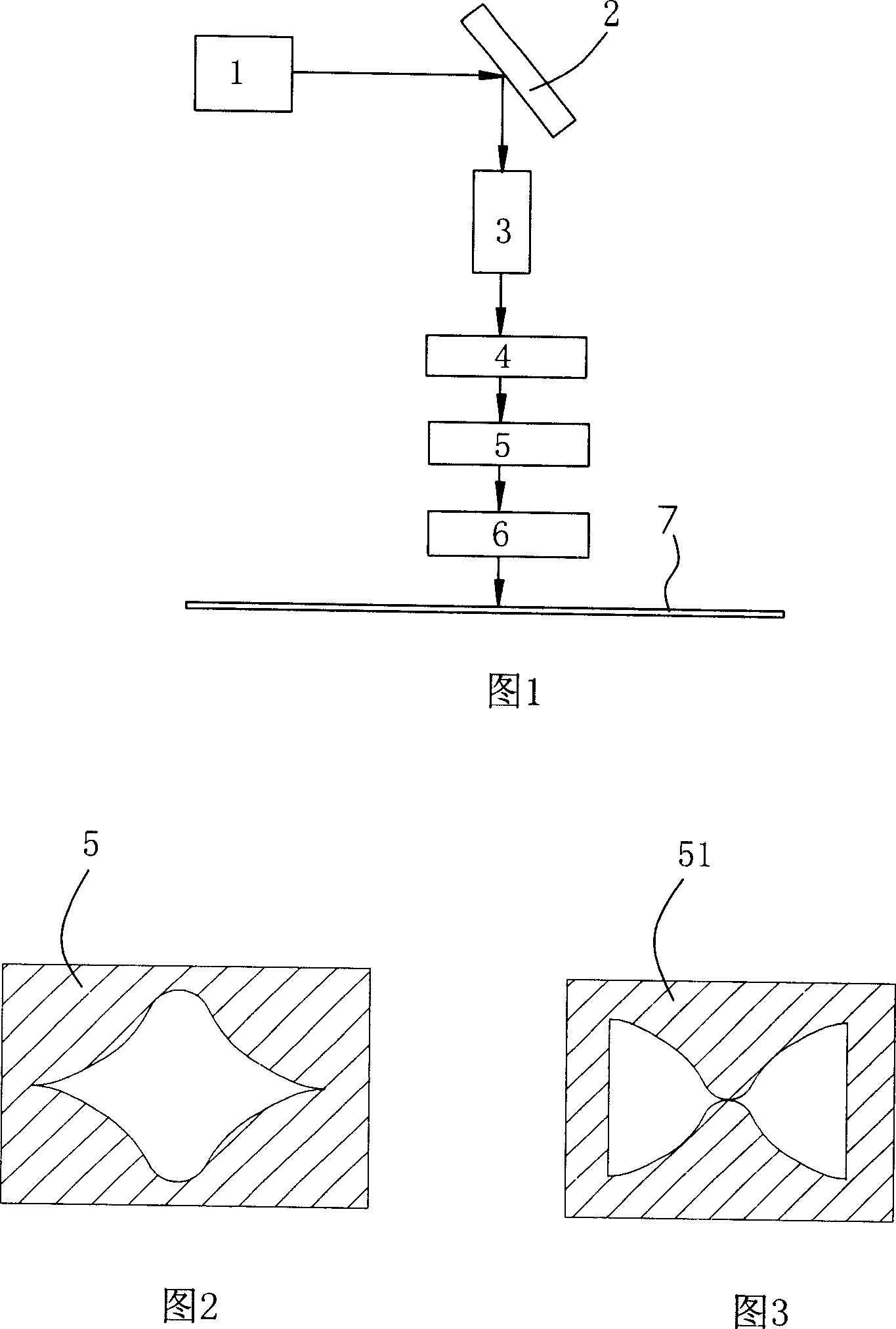
[0025] As shown in Figure 1, the production process is:

[0026] 1) Use krypton fluoride gas excimer laser 1 to generate 248nm ultraviolet light, adjust the spot size to 4mm×6mm through an adjustable diaphragm, and ensure that the spot line is parallel to the optical table;

[0027] 2) Refract the ultraviolet light generated by the excimer laser 1 at 90 degrees with the flat mirror 2, and ensure that the refracted light is also parallel to the optical table;

[0028] 3) Use a 5×10 ultraviolet light beam expander 3 to expand the ultraviolet light irradiated on the amplitude template 5, and the diameter of the spot after beam expansion is 50 mm;

[0029] 4) Use a cylindrical lens with a curvature radius of 101.7mm to longitudinally compress the spot of ultraviolet light;

[0030] 5) Vertically illuminate the amplitude template 5 shown in Figure 2 with the compressed ultraviolet light. The amplitude template is made using the Hanning window function, and its internal window size...

Embodiment 2

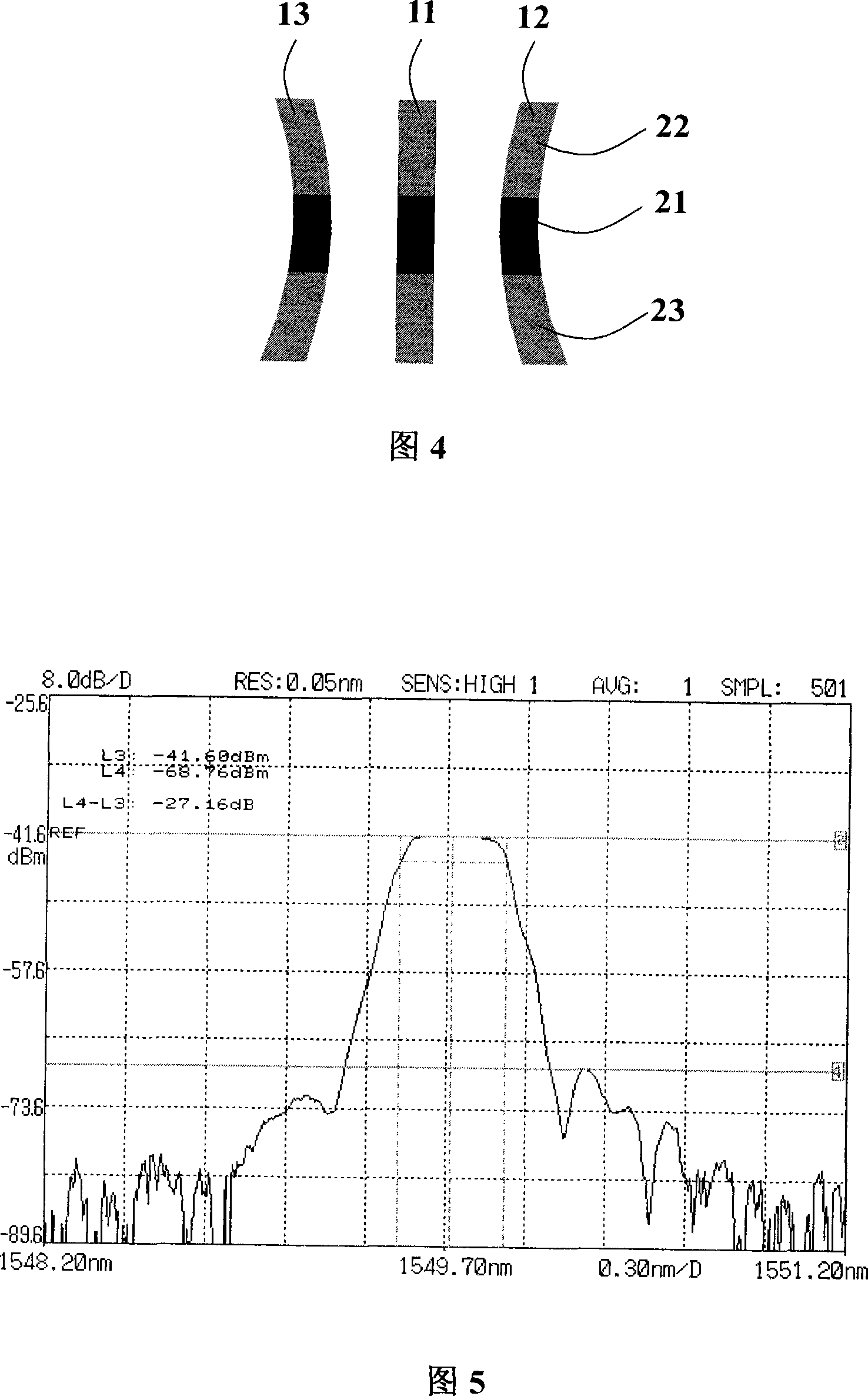
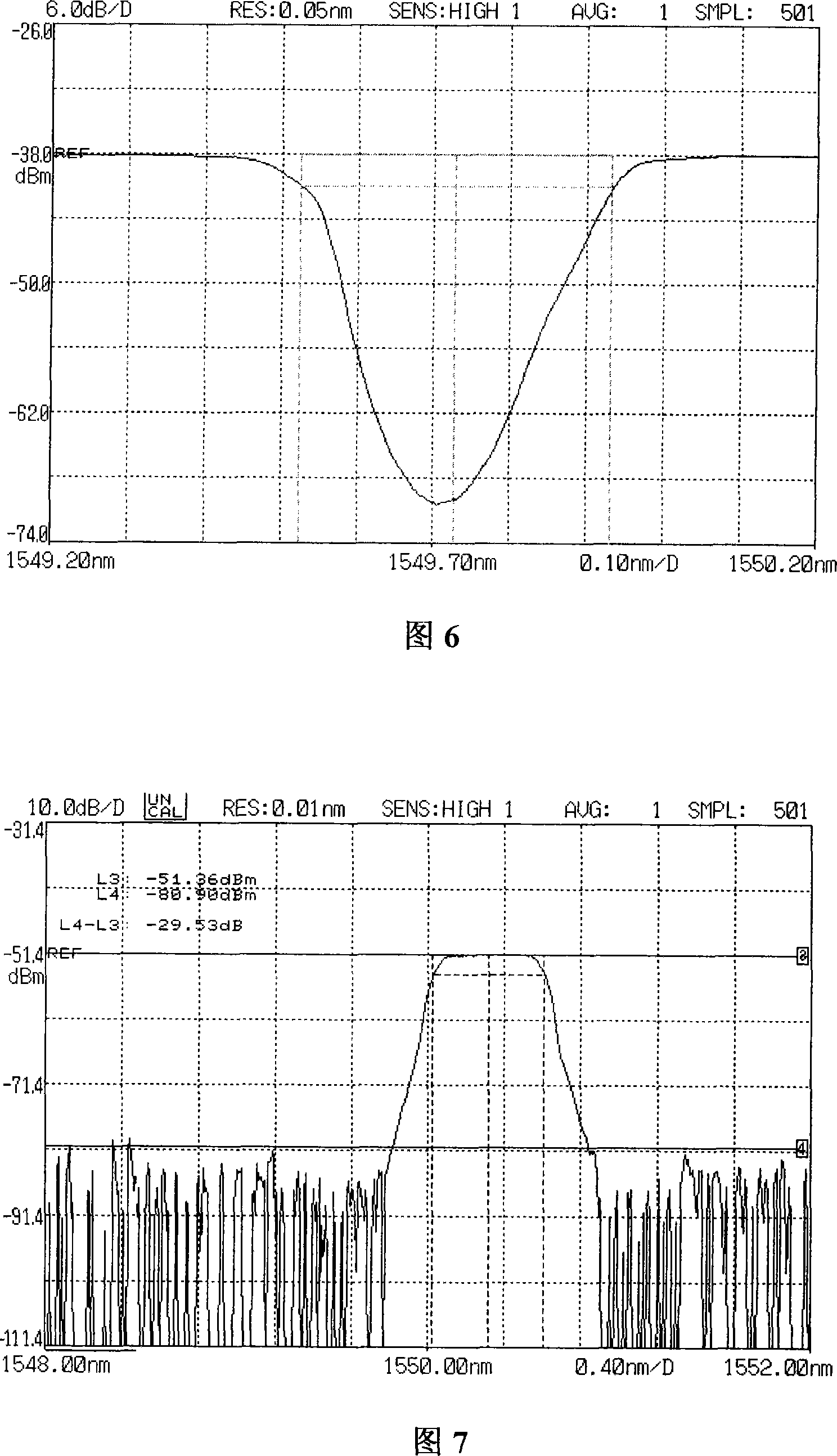
[0038] The 248nm ultraviolet light refracted by the plane mirror 2 directly passes through the cylindrical lens with a radius of curvature of 101.7mm to longitudinally compress the ultraviolet light spot, and the rest of the process is the same as in embodiment 1, wherein the window size of the amplitude template is 5mm×11mm. Its reflection spectrum and transmission spectrum are shown in Fig. 7 and Fig. 8 . It can be seen from the figure that the bandwidth of the grating is 0.588nm, the sidelobe suppression ratio is 29.53dB, the central wavelength is 1550.320nm, and the reflectivity is 99.99%.

[0039] The invention can produce a polarization maintaining fiber apodization grating with a bandwidth less than 1.0nm and a side lobe suppression ratio greater than 25dB within the wavelength range of 860nm-1610nm, and is mainly used in pump amplifiers and polarization maintaining fiber sensors.


PUM

PropertyMeasurementUnit
Wavelengthaaaaaaaaaa
Center wavelengthaaaaaaaaaa
Bandwidthaaaaaaaaaa

Abstract

The invention is a method for making polarization maintaining optical fiber apodized gratings, for obtaining fiber gratings with bandwidth less than 1.0nm and side lobe suppression ratio greater than 25dB, comprising the steps of: using quasi-molecular laser to generate UV light, and using flat reflector to make 90 deg parallel refraction on the UV light; then using columnar lens with radius of curvature of 101.7mm to vertically compress facula of the UV light after beam expansion; using the compressed UV light to vertically irradiate Hanning window function amplitude template and making amplitude modulation on the incident parallel UV light and obtaining a beam of UV light whose luminous flux is distributed according to the required apodized function; and finally using the phase template to expose photosensitive polarization maintaining optical fiber. And the invention mainly applies to pumping amplifiers and polarization maintaining optical fiber sensors in 860nm-1610nm wavelength range.

Description

technical field [0001] The invention relates to the field of optical fiber gratings, in particular to a method for manufacturing a polarization-maintaining optical fiber apodized grating. Background technique [0002] Fiber Bragg grating is a kind of fiber optic device, and its raw material is photosensitive fiber. The basic manufacturing method of fiber Bragg grating is to expose photosensitive fiber to ultraviolet light, so that the refractive index of photosensitive fiber changes periodically along the axial direction. There is a large refractive index difference between the two ends of the ordinary fiber grating and its pigtail. This refractive index difference will cause end reflection, and the existence of end reflection will seriously affect the performance of the fiber grating. It makes the reflective fiber Bragg grating such as fiber Bragg The side mode suppression ratio of gratings, chirped fiber gratings and other gratings is reduced, so that there is a large osci...

Claims


Application Information

Patent Timeline
IPC IPC(8): G02B6/02H01S3/00
Inventor 梁冰任保国何毅
Owner 西安盛佳光电有限公司
Learn More