Method of horizontally plating, electrodepositing or electrodeless plating processing on substrate

An electrodeposition, horizontal technology, applied in the field of processing, can solve the problems of coating damage, increase the production cost of large-size substrates, poor coating uniformity, etc.

Inactive Publication Date: 2008-01-23
廖智良
View PDF0 Cites 21 Cited by
  • Summary
  • Abstract
  • Description
  • Claims
  • Application Information

AI Technical Summary

Problems solved by technology

For this technology, due to factors such as the need for a vacuum environment, complex and expensive equipment, and high energy consumption, the production cost of large-size substrate applications is increased.
[0005] In terms of electroplating technology in the prior art, in addition to the well-known vertical electroplating in the industry, there is also a horizontal electroplating technology applied to circuit boards.
The vertical electroplating part is limited by the fixing, hanging and electrode configuration of the substrate, and there are difficulties such as long operation time, poor coating uniformity, difficult large-scale operatio

Method used


Image

  • Method of horizontally plating, electrodepositing or electrodeless plating processing on substrate
  • Method of horizontally plating, electrodepositing or electrodeless plating processing on substrate
  • Method of horizontally plating, electrodepositing or electrodeless plating processing on substrate

Examples


Embodiment Construction

[0024] With regard to the structure and composition of the present invention, as well as the functions and advantages that can be produced, some preferred embodiments of the present invention are described in detail as follows in conjunction with the drawings.

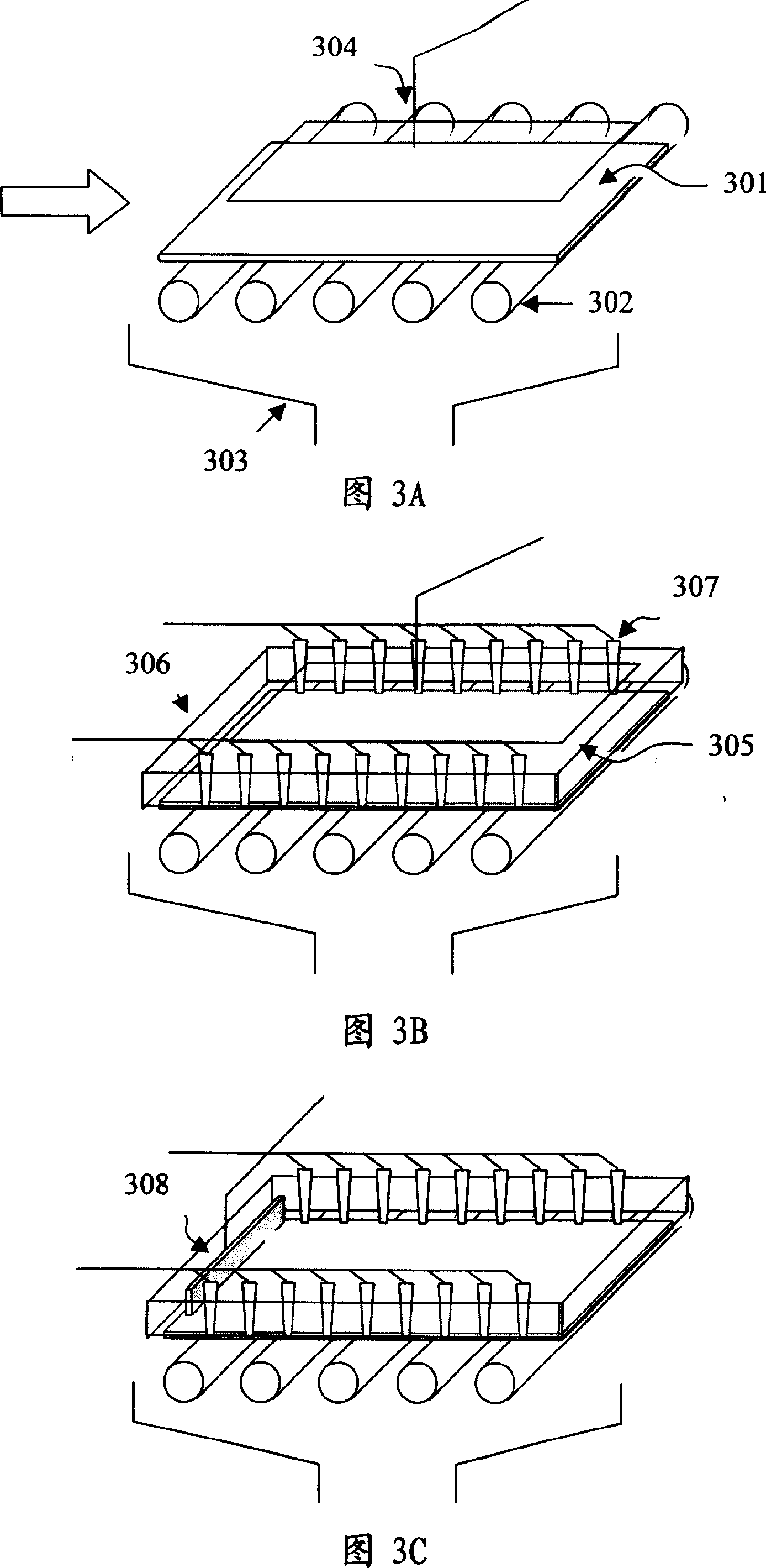
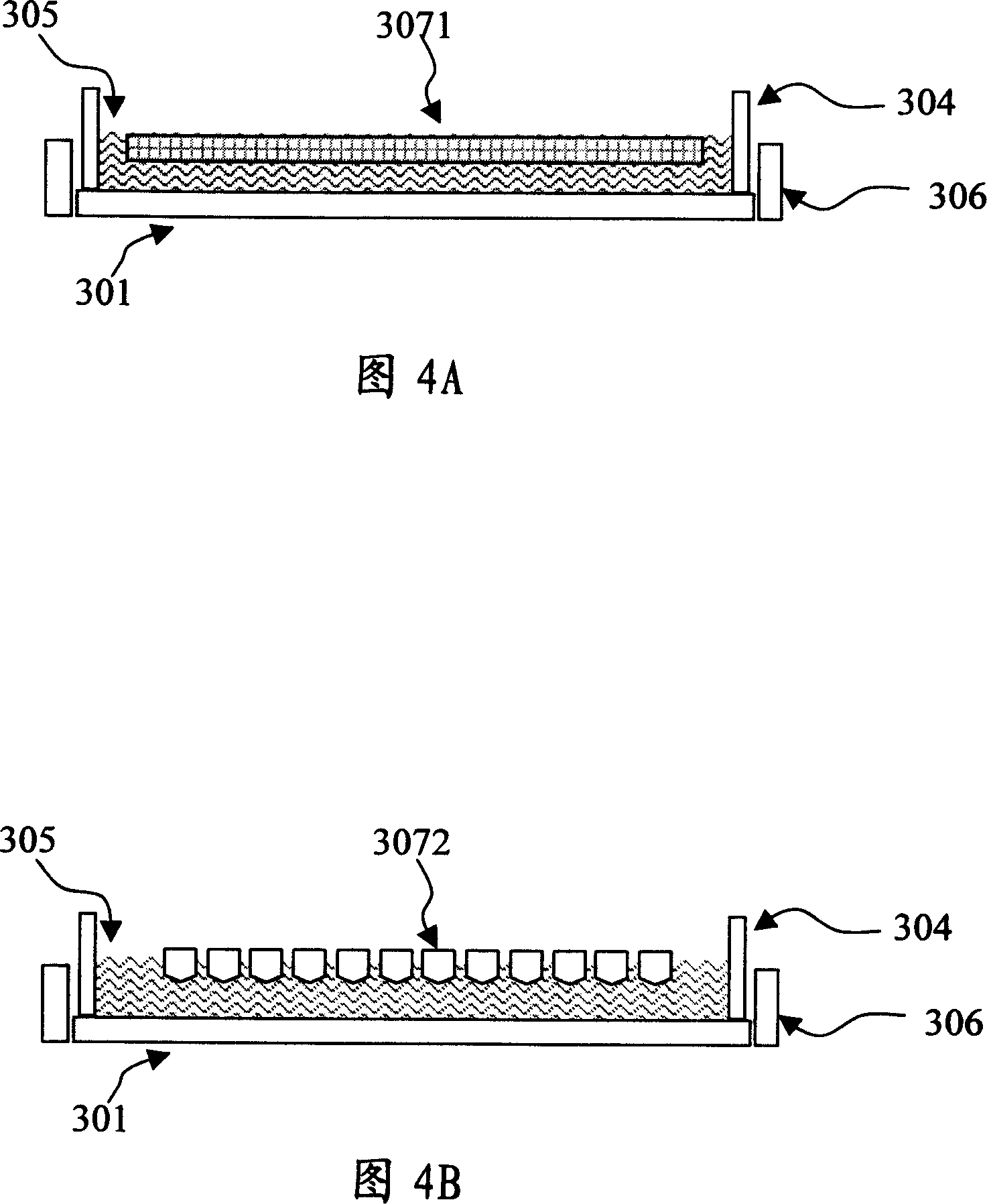
[0025] The substrate-level metal thin film and conductive material deposition structure of the present invention are shown in Figures 3A to 3C, and please refer to the flow chart in Figure 9, the procedure is to first use the driving roller or the mechanical arm (not shown) to move the substrate 301 (the present invention) In this example, a glass substrate) is sent to the substrate support system 302 for positioning. In this embodiment, the substrate support system 302 is several rollers (step 10).

[0026] After the positioning is completed, several plating solution slow flow baffles 306 are moved and attached to the edge of the substrate 301 , and these plating solution slow flow baffles 306 surround the periphery o...


PUM


Abstract

A level electroplating equipment comprises essentially a group of plating-solution baffles, a group of first electrodes, a group of reticulated, surface-like or needle-like second electrodes, and an electrode regeneration and plating-solution recycling system. When the baseplate is sent horizontally for positioning, the plating-solution slowly flowing plate and the contact cathode will clamp and conduct electricity for the baseplate; then by filling plating solution and contacting with the anode at upper, an electro plating environment is formed so as to carry out one-side plating for the baseplate at the side of cathode; or by filling electro-deposition solution and contacting with the anode at upper, an electro-deposition environment is formed, so as to carry out one-side electro deposition at the side of the anode for color optic filter pigment, dyestuff, or electro conductive photoresistor. The invention provides a level electroplating/ electro-deposition/ electrode-free electroplating equipment, can be used for electroplating an one-side even and horizontal film on the upper surface of a baseplate, for electro deposition of color optic filter pigment, dyestuff, or electro conductive photoresistor, or for depositing metallic film on a single side by chemical oxidation-reduction method.

Description

technical field [0001] The invention relates to a process for coating a film on a substrate, in particular to a processing method for performing horizontal electroplating, electrodeposition or electroless electroplating on the substrate. Background technique [0002] The electroplating / electrodeless electroplating mentioned below in this manual refers to the general inorganic metal film deposition method; electrodeposition only refers to the organic conductive material film deposition method, such as the deposition of color filter pigments, dye films or conductive photoresistors . [0003] Generally in flat panel displays or semiconductor processes, as shown in Figure 1 and Figure 2, a conductive film (aluminum, molybdenum, chromium, copper, etc. The alloy film of the main component) is mostly completed by vacuum coating technology. In other industrial applications, metals such as copper, nickel, gold, and silver are often plated on industrial products by electroplating / el...

Claims


Application Information

Patent Timeline
IPC IPC(8): C25D5/00C25D17/00
Inventor 廖彦珍
Owner 廖智良
Why Eureka
Try Eureka