Piezoelectric electroacoustic transducing device
一种电声转换器、压电式的技术,应用在压电/电致伸缩换能器、扬声器振膜阻尼、扬声器振膜形状等方向,能够解决弯曲部易塌陷、没有形成大的弯曲部、难以降低成本等问题
- Summary
- Abstract
- Description
- Claims
- Application Information
AI Technical Summary
Problems solved by technology
Method used
Image

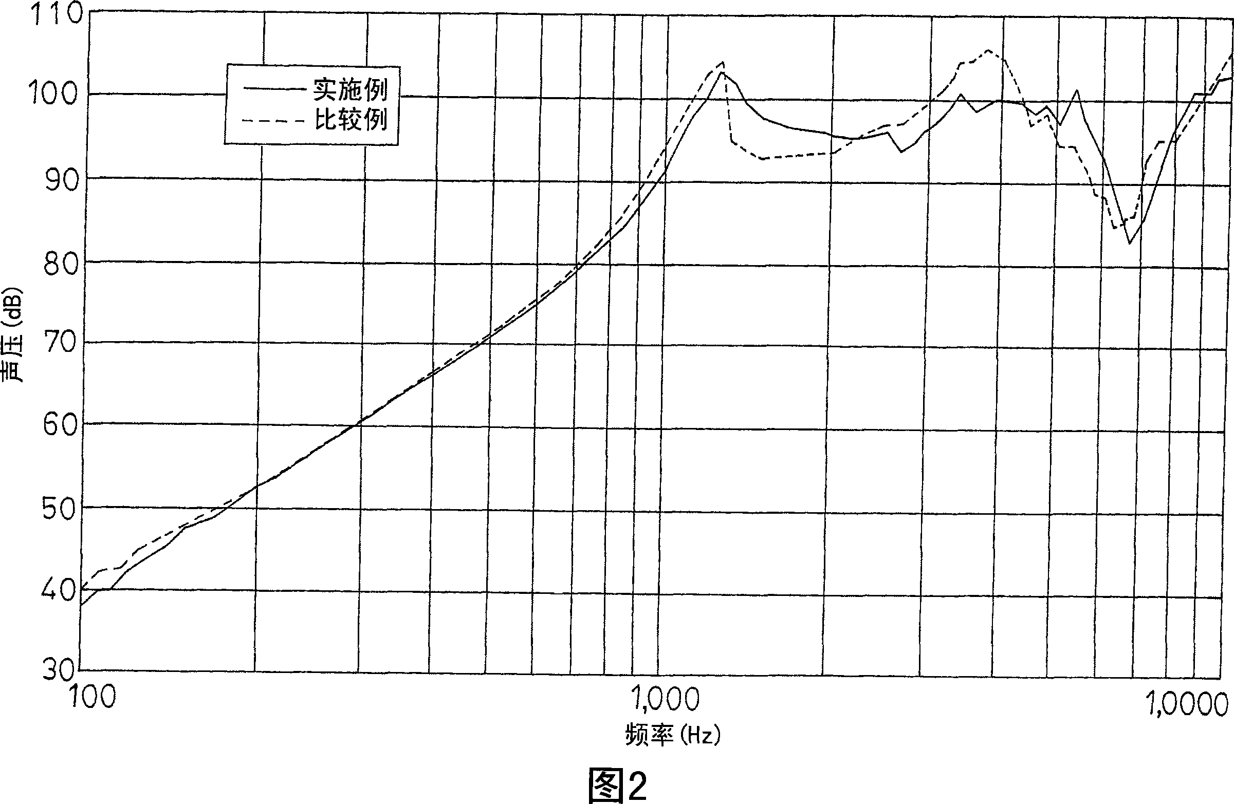
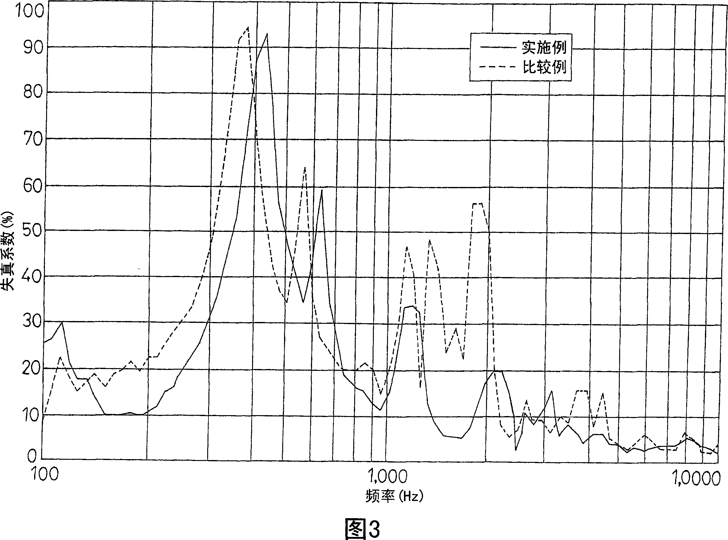
Examples
Embodiment Construction
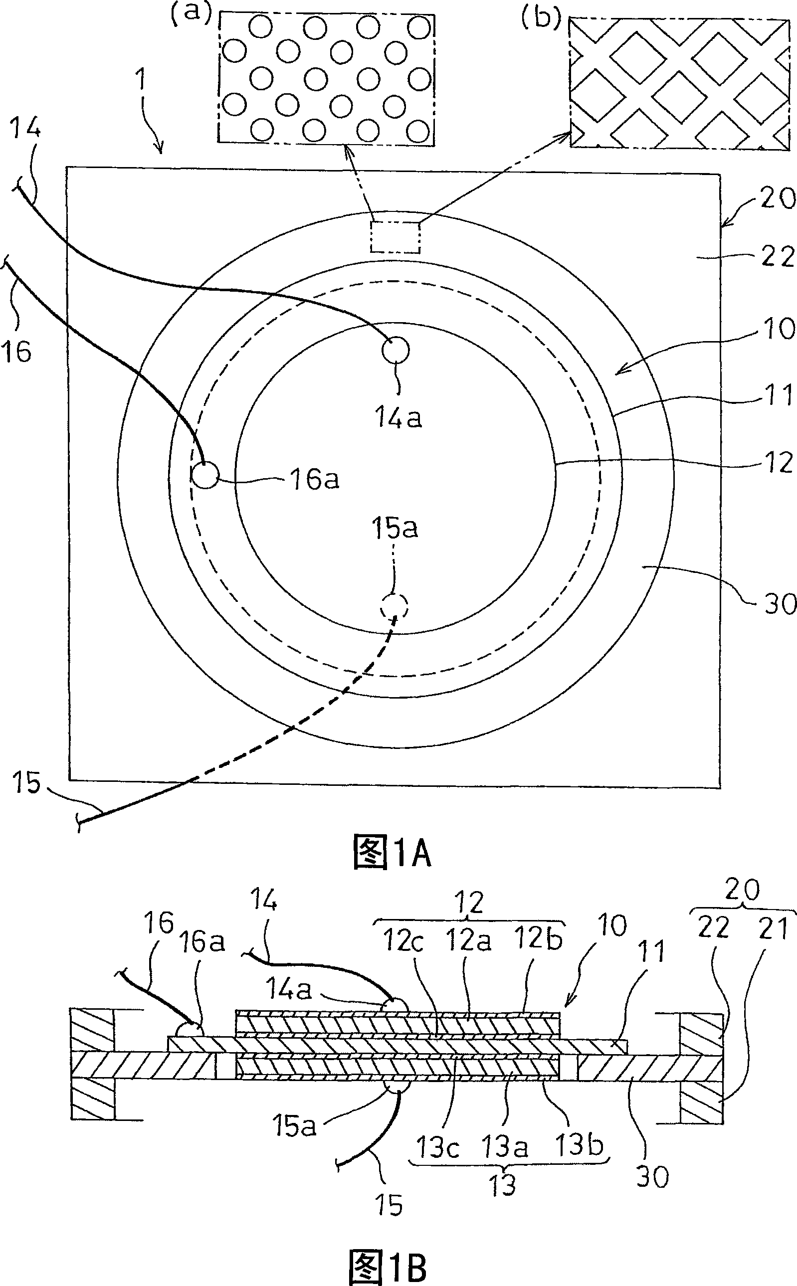
[0012] Next, a piezoelectric electroacoustic transducer 1 according to an embodiment of the present invention will be described with reference to the drawings. As shown in FIGS. 1A and 1B, the piezoelectric electroacoustic transducer 1 is composed of the following components: a frame 20; Thin disk-shaped first and second piezoelectric elements 12 and 13 , and a ring-shaped support member 30 are provided between the piezoelectric vibrator 10 and the frame 20 to support the peripheral portion of the piezoelectric vibrator 10 .
[0013] The diameter of the metal plate 11 (the diameter of the piezoelectric vibrator 10) is larger than the diameters of the first and second piezoelectric elements 12, 13. Although the first and second piezoelectric elements with the same diameter (same surface area) are shown in FIGS. 1A and 1B two piezoelectric elements 12, 13, but it is also possible to use first and second piezoelectric elements 12, 13 with different diameters.
[0014] For the me...
PUM
 Abstract
Description
Claims
Application Information