Method and device for measuring liquid thermal conductivity factor

A technology of thermal conductivity and liquid, which is applied in the field of measuring liquid thermal conductivity, can solve the problems of low practical value and insufficient estimation of heat loss, etc., and achieve the effects of simple and easy testing, wide application range and simple formula derivation

Inactive Publication Date: 2008-01-30
吴永刚
View PDF0 Cites 28 Cited by
  • Summary
  • Abstract
  • Description
  • Claims
  • Application Information

AI Technical Summary

Problems solved by technology

It seriously underestimates the heat loss, the measured result is far from the actual value, and the practical value is very low

Method used


Image

  • Method and device for measuring liquid thermal conductivity factor
  • Method and device for measuring liquid thermal conductivity factor
  • Method and device for measuring liquid thermal conductivity factor

Examples


Embodiment 1

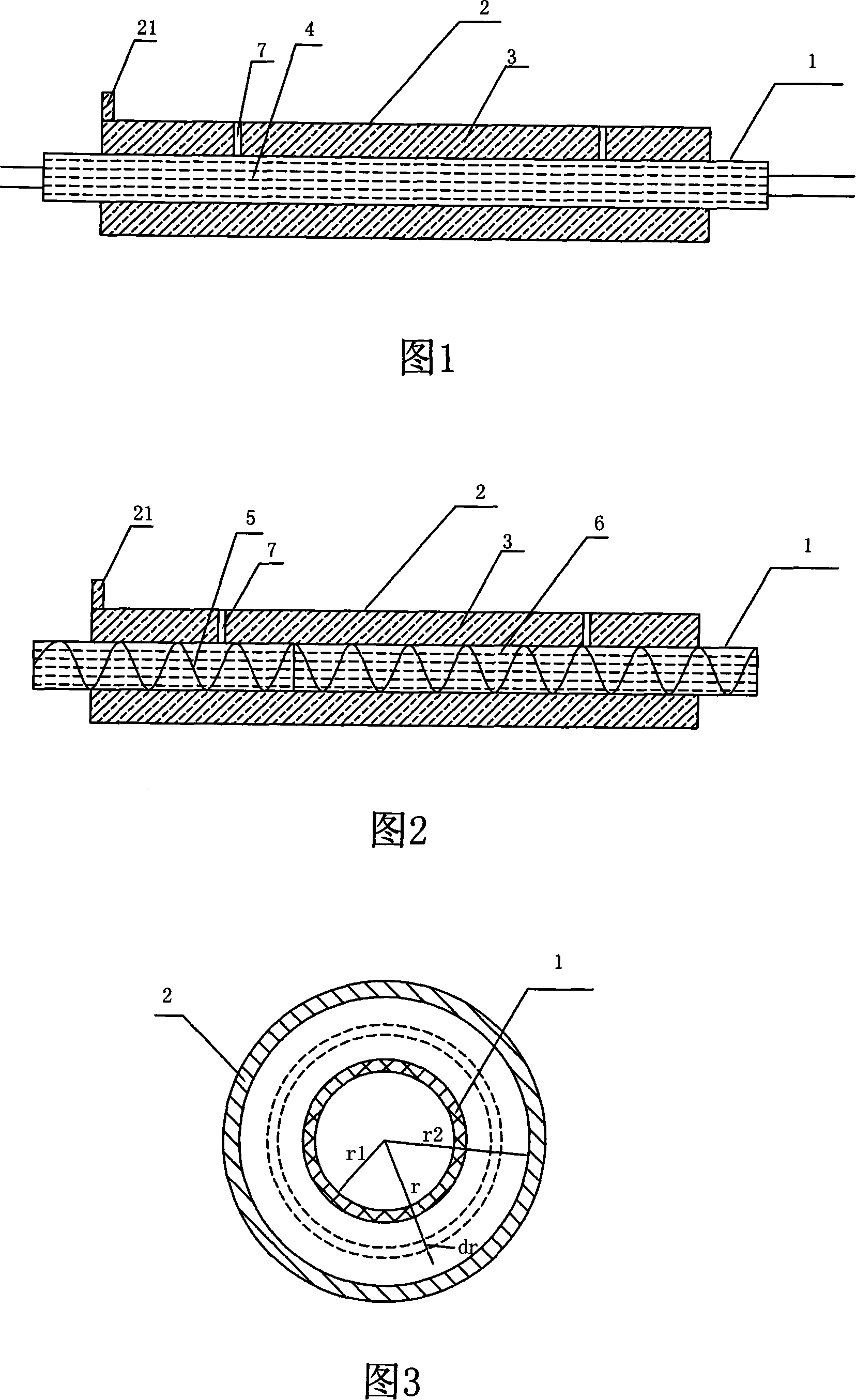
[0077] For the liquid to be tested is a high-temperature-resistant liquid, the center of the double-layer tube in this embodiment must be coaxial, and it must be resistant to a high temperature of at least 100 degrees. As shown in Figure 1, the outer tube 2 is long 2 to 5 centimeters, sealed, and the ratio of the outer tube length to the outer tube radius is greater than 10, and the outer wall is provided with an inlet 21 of the liquid to be measured (the height is 2 mm-8 mm, and the aperture is 8 mm. mm); the inner tube 1 is 33 cm long, and the two ends are respectively 4 cm longer than the outer tube, so as to connect other instruments. Two holes are respectively arranged on the side of the outer tube to install the thermocouple 7 . The diameter of the holes is 2 mm, the distance between the two holes is 135 mm, and the distance from the two ends of the tube is 55 mm. The thermocouple 7 is electrically connected with a microvoltage measuring instrument or a DC potentiometer...

Embodiment 2

[0112] For high temperature flammable liquids, the inner tube temperature is too high is very dangerous. Therefore, this embodiment is improved on the basis of the first embodiment, so as to be applicable to the measurement of the thermal conductivity of high-temperature flammable liquids.

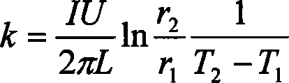
[0113] As shown in Figure 2, the dimension structure of the double-layer pipe is the same as that of Embodiment 1, but the heating method of the inner pipe is different. The inner tube 1 is fixed with a heating wire 5 and filled with a high temperature resistant liquid 6 and sealed. The outer tube 2 is filled with the liquid 3 to be tested.

[0114] During the test, the liquid to be tested is injected from the injection port 21 of the outer tube. The inner tube 1 is provided with a heating wire 5 and injected with a high temperature resistant liquid 6, and the function of filling the high temperature resistant liquid 6 is to increase the heat conduction speed. The heating wire 5 is conne...


PUM


Abstract

The invention discloses a method for measuring liquid thermal conductivity coefficient and the device thereof. The invention adopts homeostasis hotline principle to measure liquid thermal conductivity coefficient. The calculation formula of the liquid thermal conductivity coefficient is used when different heat sources are applied under the condition of one dimensional conduction respectively deduced by Fourier heat conduction basic law. Then the heat generated by the heating resource which is transmitting heat. And the liquid thermal conductivity coefficient is calculated by measuring the temperature difference at particular points in heat conduction direction when heat balanced. High-temperature resistant coaxial double-layer pipes are used as outer pipes while heat stable heating tube used as inner pipes. Liquid to be measured is packed in the space between the inner and the outer pipes. The ratio of the length of the outer pipe to the external diameter of the outer pipe exceeds is greater than 10. The way of heating of the inner pipe adopts constant-temperature and uniform-speed circulating water or tempering wire and filled with high temperature resistant liquid at the same time. The former is suitable for common liquid and the latter for high temperature flammable liquid. The invention has the advantages of simple structure, large serviceable range and high accuracy rating, thus measuring the coefficients of heat conductivity of various liquids simply and precisely is possible.

Description

【Technical field】 [0001] The invention relates to a method and device for measuring thermal conductivity, in particular to a method and device for measuring liquid thermal conductivity. 【Background technique】 [0002] In the field of heat exchange technology, as long as there is a temperature gradient in a system, or two systems with different temperatures come into contact, energy transfer will occur. It exists only during migration, and it can neither be measured nor observed directly, but its effects can be observed and indirectly measured. This process of energy transfer due to temperature difference is collectively referred to as "heat transfer". [0003] All heat transfer processes include energy transfer and conversion. The temperature difference is the driving force of all heat transfer phenomena and a necessary condition for heat transfer between objects. Because the mechanism of heat transfer is very complicated, it not only varies with the temperature differenc...

Claims


Application Information

Patent Timeline
Patent Type & Authority Applications(China)
IPC IPC(8): G01N25/20G01N25/18
Inventor 吴永刚
Owner 吴永刚
Why Eureka
Try Eureka