Heat exchange piece and piece type air heat exchanger using same

An air heat exchanger, heat exchange fin technology, applied in heat exchange equipment, heat exchanger types, indirect heat exchangers, etc., can solve the problems of reducing heat exchange efficiency, large volume, heat conduction failure, etc., to eliminate heat exchange Dead point, increase the heat dissipation area, the effect of reasonable structure setting

Inactive Publication Date: 2008-02-06
天津市研翔电子科技有限公司
View PDF0 Cites 7 Cited by
  • Summary
  • Abstract
  • Description
  • Claims
  • Application Information

AI Technical Summary

Problems solved by technology

In order to obtain higher heat exchange efficiency, products with various structural forms have been developed. The more commonly used sheet air heat exchanger is composed of a heat exchanger core and a fixing mechanism. The heat exchange fins of the heat exchanger core are made of The partition plate and the fixed fins on it are composed of the bottom plate, the vertical baffles at both ends of the bottom plate and the sealing edges on the baffle. The heat exchanger core is formed by grouping opposite sides. The fin structure can increase the heat exchange area and improve the heat exchange efficiency. However, the disadvantage is that the fins and partitions are connected by welding and bonding, and the connection parts are prone to heat conduction failures, which affect the heat exchange effect, and the structural shape of the fins and partitions makes the wind resistance large, which is very difficult. It is difficult to obtain enough air volume. Although it can adjust the temperature when used in the electrical cabinet, it cannot achieve the purpose of timely cooling the local overheating in the electrical cabinet, and the safety protection is poor. In addition, its structure is complex and bulky, and structural parts such as fins and partitions The use of expensive materials such as aluminum plates, copper plates, and steel plates increases the weight and is limited for use in outdoor electrical cabinets
[0003] In view of the above-mentioned defects, there is an integrated heat exchange sheet made of copper, aluminum and other metal foils in the market. Metal foil molded parts, multi-layer heat exchange fins are stacked and stacked with the convex and concave top surfaces of the conical frustum between two adjacent layers, and the adjacent layers are staggered and closed in turn. Two groups of opposite sides perpendicular to each other are connected to form a heat exchange The core is fixed by the frame to form two sets of mutually perpendicular air ducts that are isolated from each other. Compared with the aforementioned finned heat exchange fins, it has a compact structure, small size and light weight, appropriate air resistance, increased air volume, and convex , The shape of the concave truncated cone has a better turbulent effect, so the heat transfer efficiency is improved, but through experiments and actual use observations, this kind of heat exchange fin with convex and concave conical truncated still has structural defects. In use, when the airflow is in When passing through the air duct with truncated cones, it flows downstream after passing through both sides of the truncated cones, forming a large airflow stagnation area on the back of the truncated cones, that is, the heat exchange dead zone, which reduces the heat exchange efficiency; The shape is smaller than the surface area of ​​other configurations with the same size, which also affects the heat exchange effect
In addition, the heat exchanger core of the existing plate-type air heat exchanger is in use, and its cold and hot airflows pass through the air duct along the direction perpendicular to each other, and the fans are installed on the two vertical sides of the heat exchanger core. It is only suitable for installation on the top of the outdoor electrical cabinet. For the heat exchanger installed on the cabinet wall and door, due to the limited width and space of the appliance, the heat exchange fins should not extend in the direction perpendicular to the cabinet wall and door surface, so fans are required. Installed on the upper and lower sides of the heat exchanger core along the vertical wall
In short, with the development of electronics, communications, and electric power, for some electrical cabinets placed outdoors for communication base stations and monitoring systems, in view of the large number of equipment in the cabinets, the power consumption is large to avoid local overheating, and heat exchangers are required to provide larger Higher air volume to provide higher protection, the market urgently needs the advent of heat exchangers with large air volume, high heat exchange efficiency and high protection level

Method used


Image

  • Heat exchange piece and piece type air heat exchanger using same
  • Heat exchange piece and piece type air heat exchanger using same
  • Heat exchange piece and piece type air heat exchanger using same

Examples


Embodiment 1

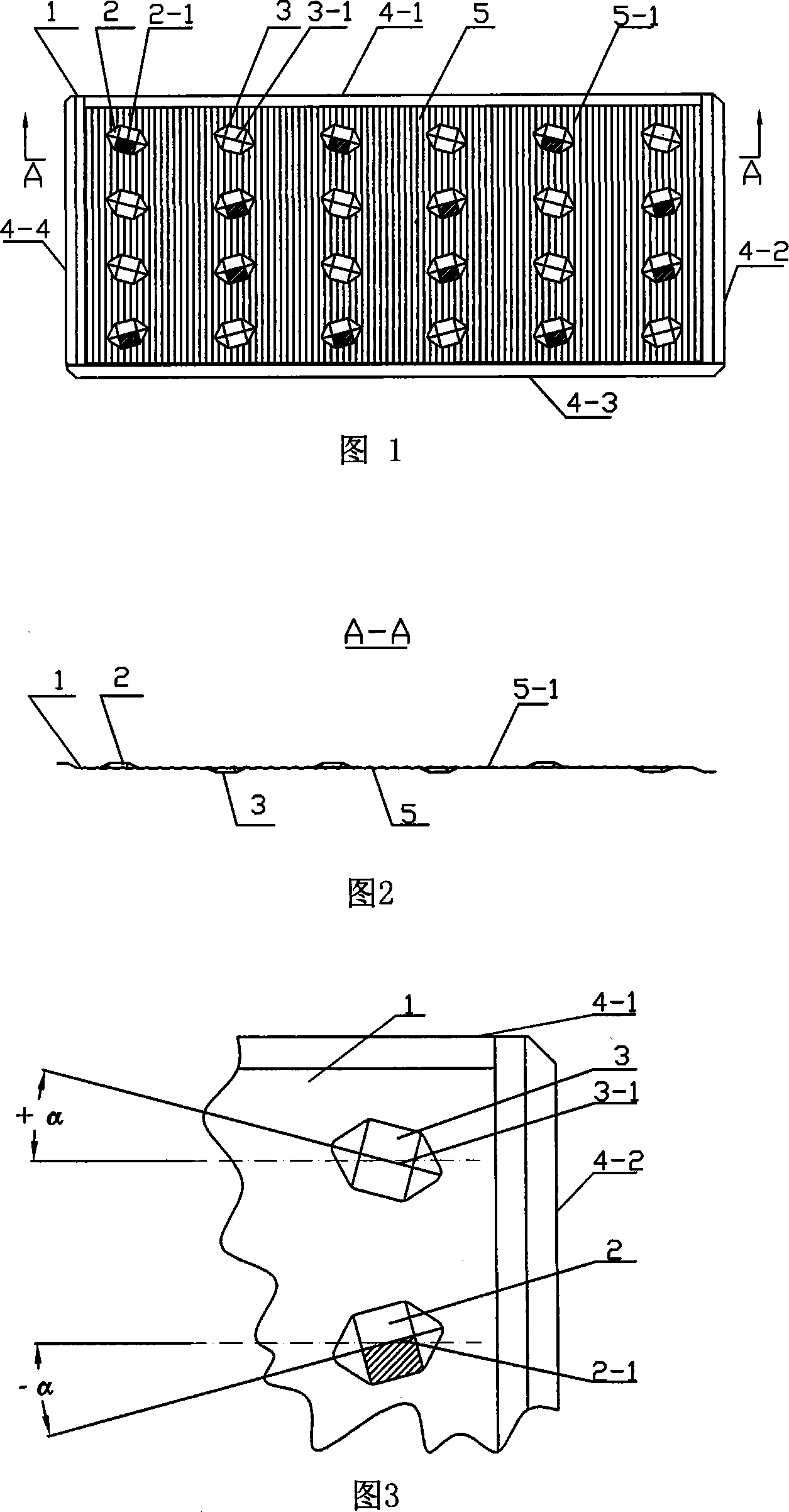
[0030] Fig. 1 is a schematic front view of the heat exchange fin; Fig. 2 is a cross-sectional view of A-A of Fig. 1; Fig. 3 is a schematic diagram of the inclination angle of the central ridge of the convex and concave polyhedron shells in Fig. 1 . Figures 1-3 show a heat exchange fin 1, which is a metal foil molded part composed of a substrate 5 and several convex and concave shell units arranged vertically and horizontally on it, which is characterized in that the convex 1. The concave shell type unit is a convex and concave polyhedral shell 2, 3 symmetrical to the central ridge 2-1, 3-1 respectively, and its central ridge 2-1, 3-1 is connected to the heat exchange fin 1 and the air inlet direction The included angle between the parallel sides 4-1 is +α or -α, and the value of α is 10° to 45°. The dotted line in Fig. 3 is the side 4-1 parallel to the air inlet direction of the heat exchange fin 1 Parallel lines, in this case the alpha value is 15°. The substrate 5 of the he...

Embodiment 2

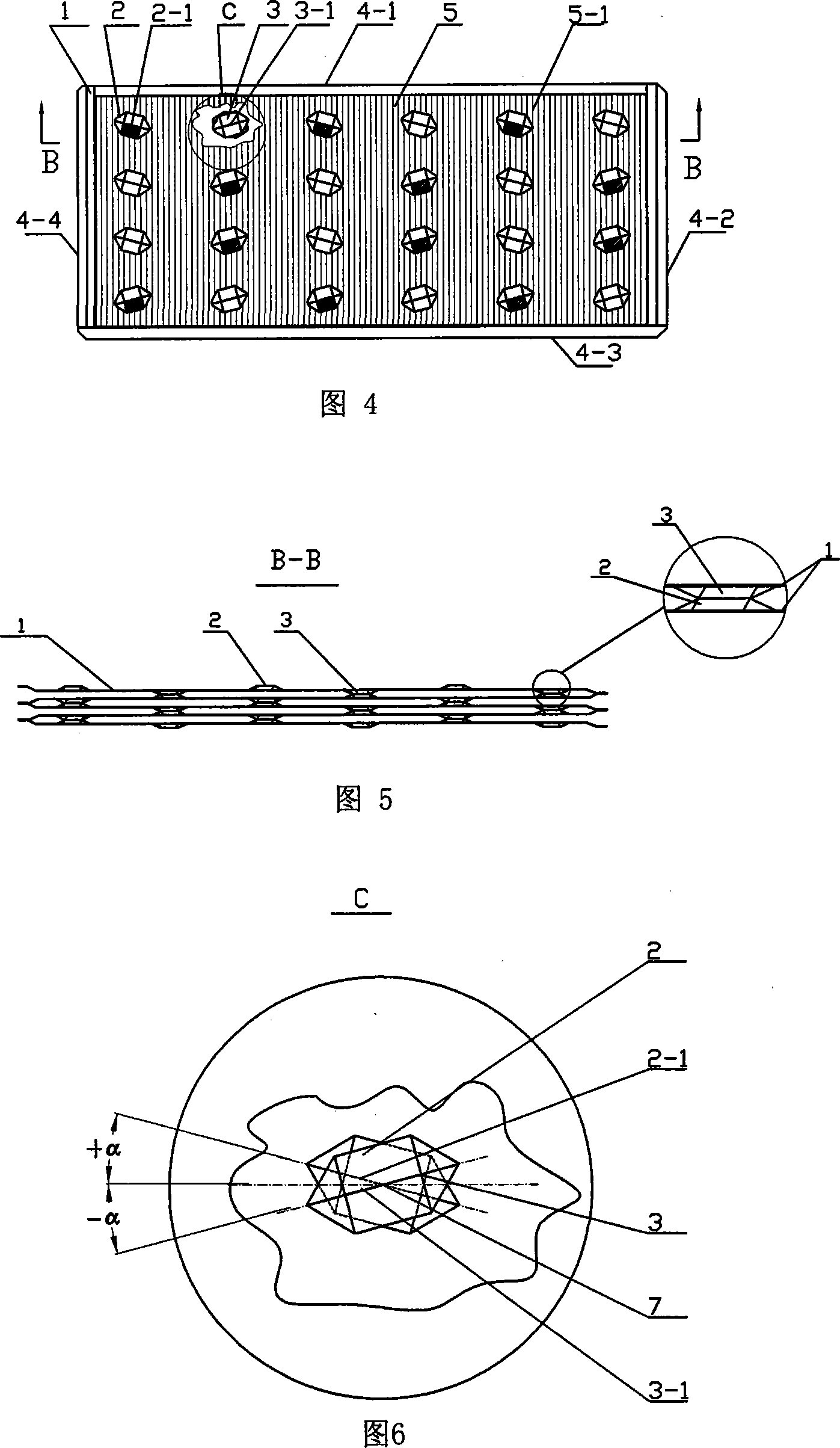
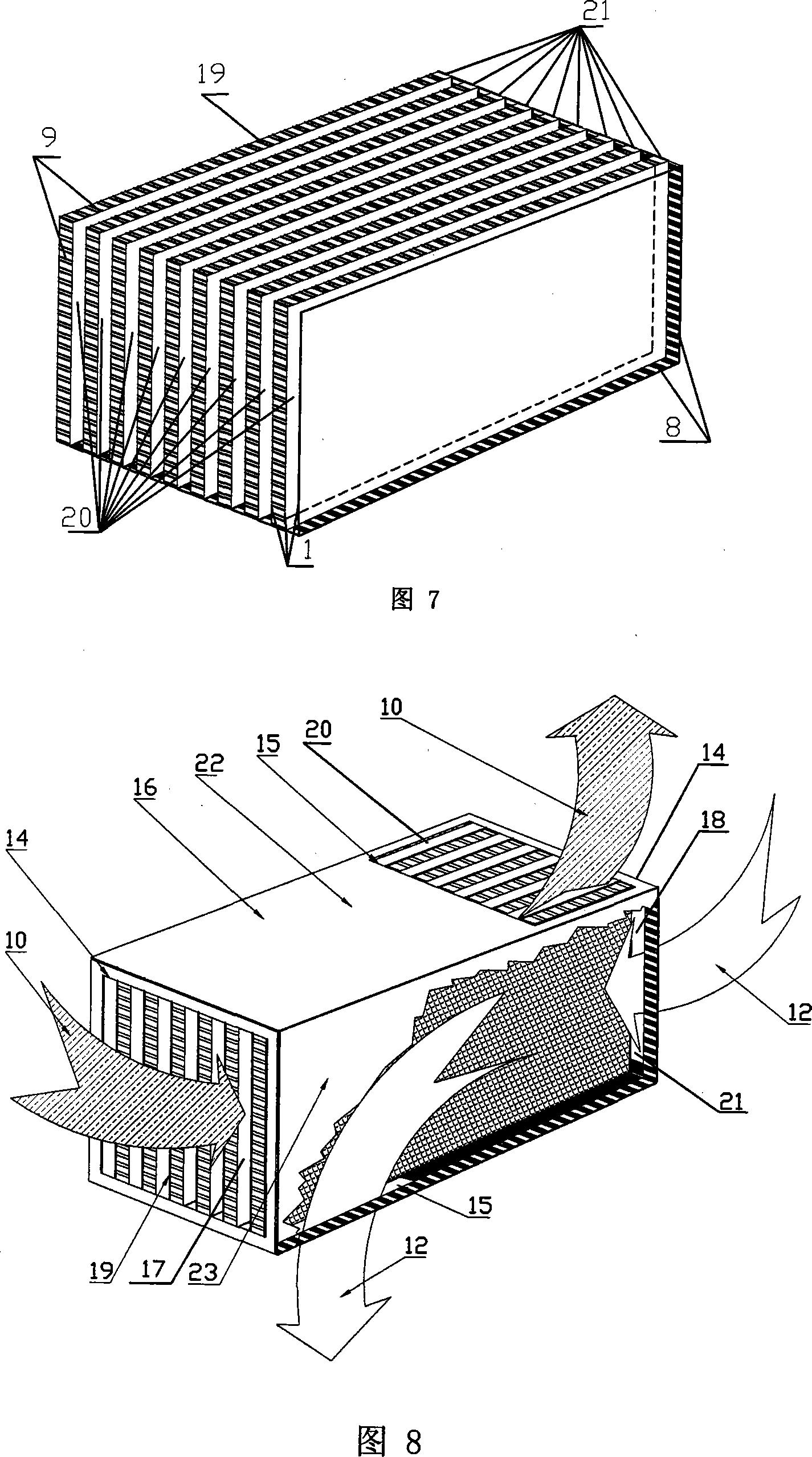
[0032] Fig. 4 is a schematic diagram of the front structure of the convex and concave polyhedral shells of two adjacent heat exchanging fins intersecting against each other; Fig. 5 is a cross-sectional view of B-B in Fig. 4; Fig. 6 is the center of two adjacent heat exchanging fins in Fig. 4 Schematic diagram of the positions of the convex and concave polyhedral shells with intersecting ridges; Fig. 7 is a schematic structural diagram of the sealed connection of the heat exchange fins of the core of the sheet air heat exchanger; Fig. 8 is a schematic diagram of the overall structure and working principle of the sheet air heat exchanger; Fig. 9 is a schematic diagram of the installation structure of the plate-type air heat exchanger installed on the side wall of the electrical cabinet. Fig. 8 shows a plate-type air heat exchanger using the heat exchange fins 1 described in Embodiment 1, which includes a heat exchanger core 19 and a fixing mechanism composed of multiple layers of...


PUM


Abstract

The present invention relates to a heat exchange chip and a chip type air heat exchanger, the heat exchange chip which adopts a metal foil mold compressed piece consists of a base chip and a metal leaf die pressing element arranged vertically, horizontally and crosswise, and composed of a plurality of convex and concave casing type units. The present invention is characterized in that the convex and concave casing type units are convex and a concave multi-surface casings being symmetrical to a central ridge, the included angle between the central ridge and the side of the heat exchange chip parallel to the air intake direction is plus Alpha or minus Alpha, the value of the Alpha is 10 degrees to 45 degrees; the chip type air heat exchanger is characterized in that the heat exchange chip is adopted, a plurality layers of heat exchange chips are folded and arranged in rows through the central ridge of the convex and the concave multi-surface casing between two adjacent layers, and one side connecting edge corresponding the two adjacent layers or the other symmetrical side connecting edge are consecutively and orderly connected, to form a heat exchanger core; a guide flow fixing box is suited at the outer part of the heat exchanger core. The present invention has the advantages of large amount of wind flow, high efficiency of heat exchanging, good protection performance, severe structure, small size and light weight, and the present invention is suitable for outdoor electrical cabinet.

Description

technical field [0001] The invention relates to the technical field of air heat exchangers, in particular to a heat exchange fin with large air volume and high heat exchange efficiency suitable for outdoor electric cabinets and a plate-type air heat exchanger using the heat exchange fin. Background technique [0002] As an air-air heat exchange device, the plate air heat exchanger is used in air conditioners, exhaust waste heat recovery devices and outdoor electrical cabinets. Its structure is generally stacked by multi-layer square heat exchange fins, and adjacent layers are staggered and sealed to connect two sets of sides perpendicular to each other to form mutually isolated air inlet and exhaust channels. And the relative flow heat exchange on the surface of the air inlet channel and the conduction heat exchange between the air channels to realize the heat exchange of cold and hot air. In order to obtain higher heat exchange efficiency, products with various structural ...

Claims


Application Information

Patent Timeline
Patent Type & Authority Applications(China)
IPC IPC(8): F28D9/02F28F3/04
Inventor 魏鸿琪
Owner 天津市研翔电子科技有限公司
Why Eureka
Try Eureka