
Axial switch reluctance motor

A switched reluctance motor, axial technology, used in motors, electric vehicles, electrical components and other directions, can solve the problem of reducing the rotating magnetic flux, the axial switched reluctance motor has not been mentioned, and achieves improved rotating force and simple structure. , The effect of convenient installation and maintenance

Inactive Publication Date: 2008-02-06
JIANGSU UNIV
View PDF2 Cites 13 Cited by
  • Summary
  • Abstract
  • Description
  • Claims
  • Application Information

AI Technical Summary

Problems solved by technology

Therefore, it is of great significance to consider changing the traditional motor transmission mode, especially the energy transmission in the axial direction, such as the disc motor with the application number 85203304 and the axial air gap motor with the application number 87217225, and the axial air gap with the application number 87217225 The motor overcomes the disadvantage of excessive magnetic pull on one side of the disc motor with application number 85203304. Two stators are used on both sides of the rotor and arranged symmetrically to balance the magnetic pull on both sides. However, the rotor passes through the two stators. Forms a flux loop, greatly reducing the effective rotating flux
[0004] At present, there is no mention of axial switched reluctance motors in domestic and foreign literature and patent materials.

Method used


Image

  • Axial switch reluctance motor
  • Axial switch reluctance motor
  • Axial switch reluctance motor

Examples


Embodiment Construction

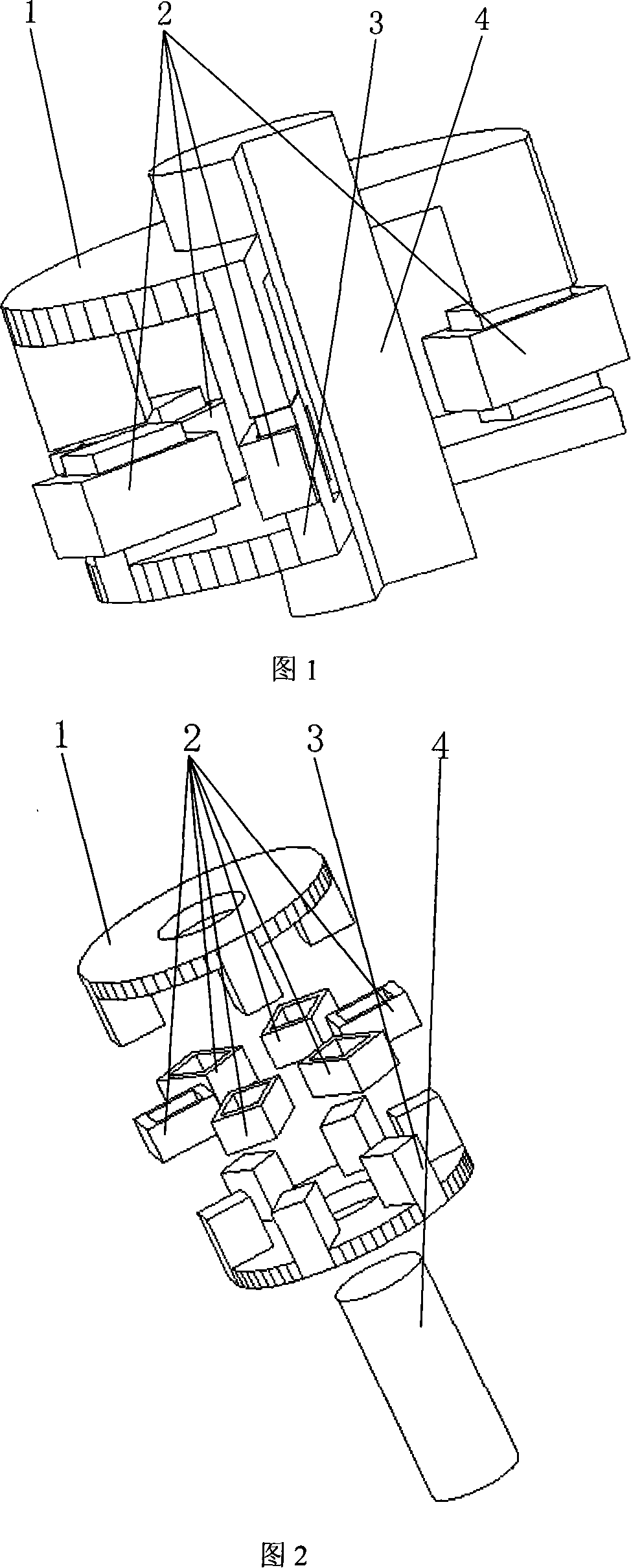
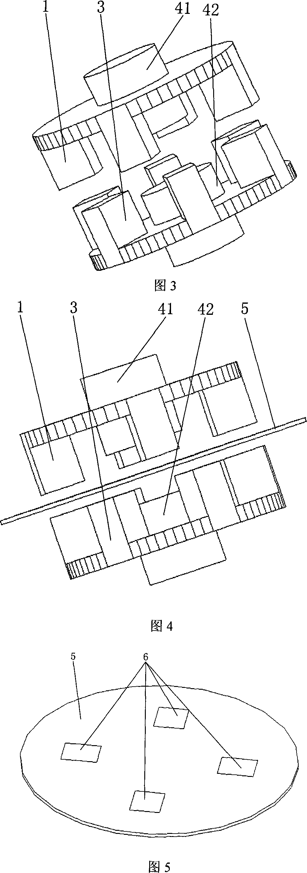
[0024] Fig. 1, 3, 4 and 6 are the axial switched reluctance motor of the present invention, stator and rotor independent shaft axial switched reluctance motor, stator and rotor isolated axial switched reluctance motor and two axial switched reluctance motors Schematic diagram of the resistance-motor combination structure.

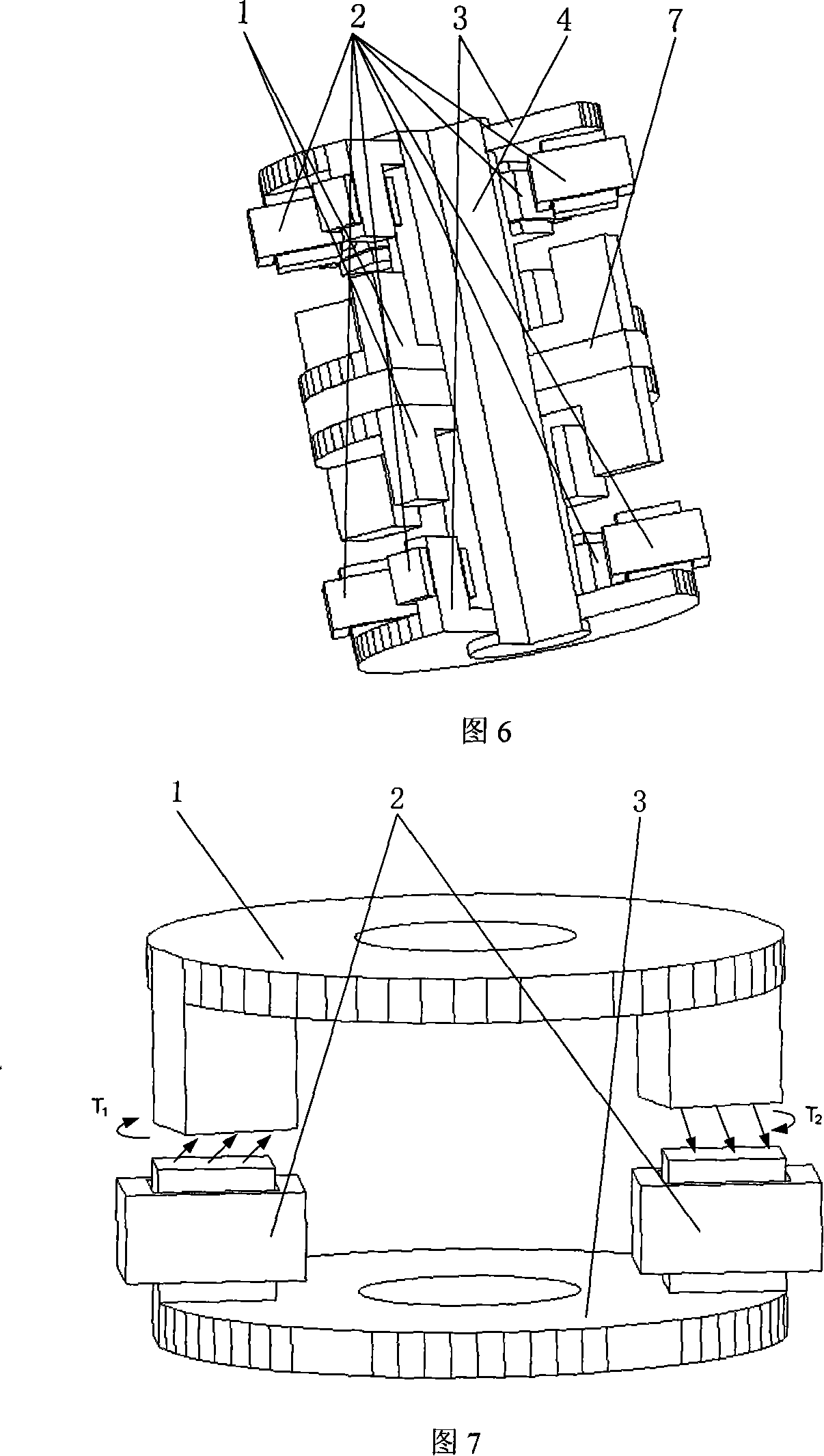
[0025] Axial switched reluctance motor, as shown in Figure 7. The magnetic field lines always try to form a loop along the path with the least reluctance, so the rotor is subjected to a clockwise rotational pull under the action of the stator winding excitation flux, thereby causing the rotor to rotate. The control method is basically the same as that of the ordinary switched reluctance motor.

[0026] The stator and the rotor can work in different environments. The stator and the rotor are separated by a special partition. There are magnetic blocks corresponding to the number of rotor poles and magnetic poles in the partition, and the size is the same as ...


PUM


Abstract

The present invention belongs to an electric transmission device filed, which is suitable for the transmission controlling in the special environment such as the electromotive vehicle filed, the food processing, the underwater operation, the nucleus industry, and the aviation field, The present invention consists of a rotor, a winding, a stator and an axis, the rotator and the stator are distributed along the axial direction. The directions of the rotator pole and the stator pole are along the axial direction, and the rotator pole and the stator pole are faced with each other along the axial direction. The pole number of the rotator and the stator can adopt the 6 to 4, 8 to 6, 12 to 8, or 4 to 6, 6 to 8, 8 to 12 and other type of the prior SRM proposal. The rotator and the stator adopt the different rotating axis, the rotator and the rotating axis can be completely separated from the stator. Due to the stator and the rotor has the distance along the axial direction, change the radial position to the axial direction relation, the radial size is decreased, the radial of the rotator is not limited, only need to form the magnetic loop with the stator at the axial direction, the energy transmission manner is changed to the direct axial direction transmission, and beneficial to the heating output of the electromotor, and suitable for using as the electromotor of the electric vehicle wheel.

Description

technical field [0001] The invention belongs to the field of electric transmission (mechanical transmission) equipment, in particular to an axial switched reluctance motor, which is suitable for transmission in the field of electric vehicles and in special environments such as food processing, wind power generation, underwater operations, nuclear industry, and aviation fields. field of control technology. Background technique [0002] In the 1980s, when the AC speed control system developed rapidly, a switched reluctance motor (SRM for short) appeared with simple structure, firmness, reliable operation, low cost, high efficiency, and good lateral torque and lateral power speed regulation performance. The speed control system composed of it has the advantages of both DC drive and ordinary AC drive. The structure of SRM's rotor without winding and stator concentric winding and its operating principle determine that it can achieve ultra-high-speed, low-loss operation and self-r...

Claims


Application Information

Patent Timeline
Patent Type & Authority Applications(China)
IPC IPC(8): H02K1/06H02K29/06
CPCY02T10/641Y02T10/64
Inventor 孙玉坤费德成全力
Owner JIANGSU UNIV
Learn More