High gain wideband amplifier circuit with temperature compensation

An amplifier circuit, temperature compensation technology, applied in the direction of improving amplifiers to reduce temperature/power supply voltage changes, improving amplifiers to expand bandwidth, improving amplifiers to improve efficiency, etc. characteristics changes, etc., to achieve the effect of increasing the gain, reducing the variation of the base current, and compensating for the temperature characteristics

Inactive Publication Date: 2008-02-06
INST OF MICROELECTRONICS CHINESE ACAD OF SCI
View PDF0 Cites 9 Cited by
  • Summary
  • Abstract
  • Description
  • Claims
  • Application Information

AI Technical Summary

Problems solved by technology

[0004] In the conventional RF wideband amplifier circuit based on Darlington tube shown in Fig. 1, the change of temperature will cause the change of junction voltage drop of transistors 11 and 12eb, thus resulting in a large change of output characteristics with temperature
Moreover, since the amplifier circuit is used as a broadband amplifier circuit, in order to have a larger output power, the ratio of the resistor 22 to the resistor 21 cannot be too large, so it is necessary to introduce negative feedback into the amplifier circuit, causing the amplifier circuit to be in a deep negative feedback state. In turn, the gain of the amplifier circuit becomes smaller, which seriously affects the gain of the amplifier circuit.

Method used


Image

  • High gain wideband amplifier circuit with temperature compensation
  • High gain wideband amplifier circuit with temperature compensation
  • High gain wideband amplifier circuit with temperature compensation

Examples


Embodiment Construction

[0028] In order to make the object, technical solution and advantages of the present invention clearer, the present invention will be described in further detail below in conjunction with specific embodiments and with reference to the accompanying drawings.

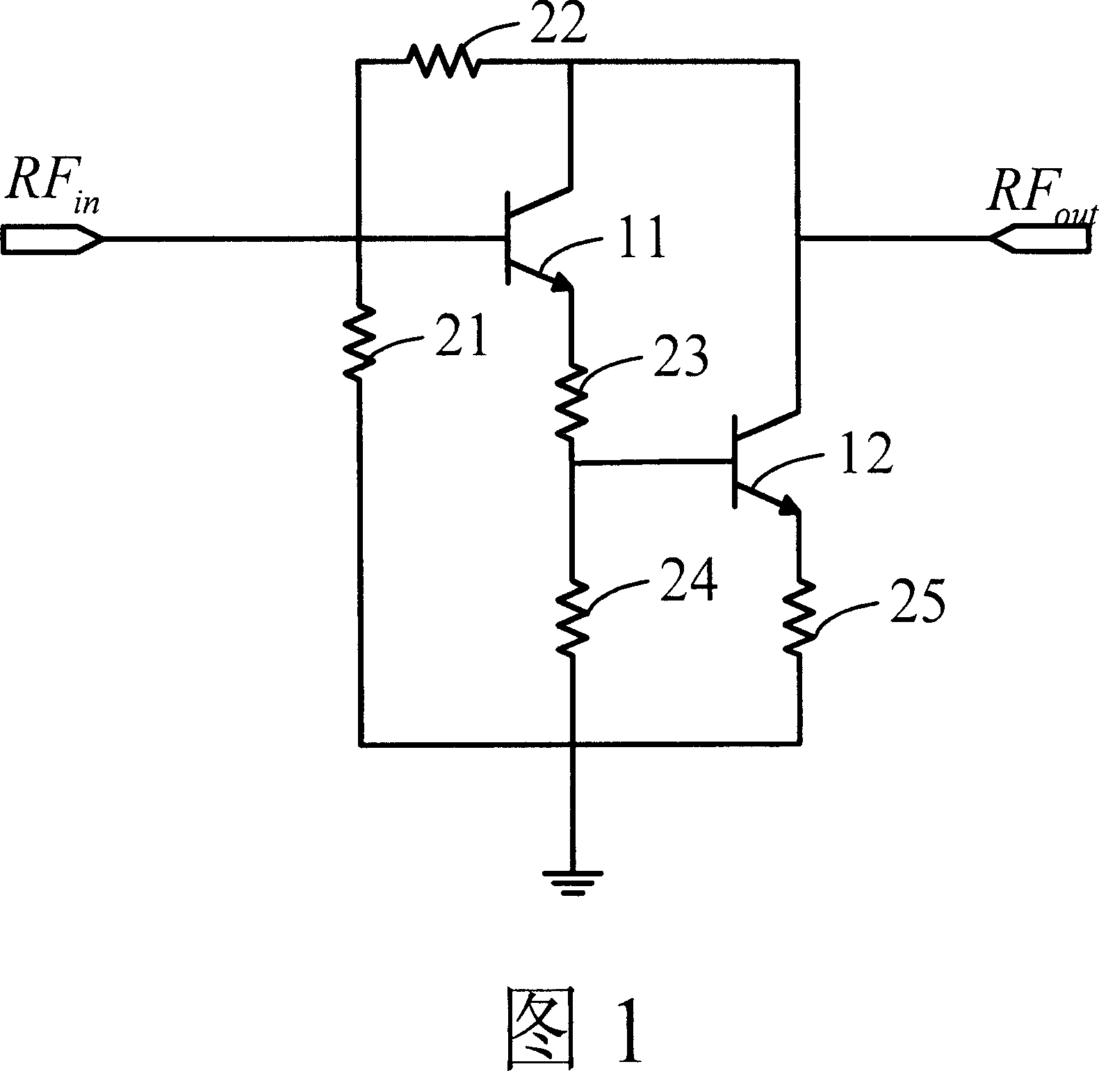
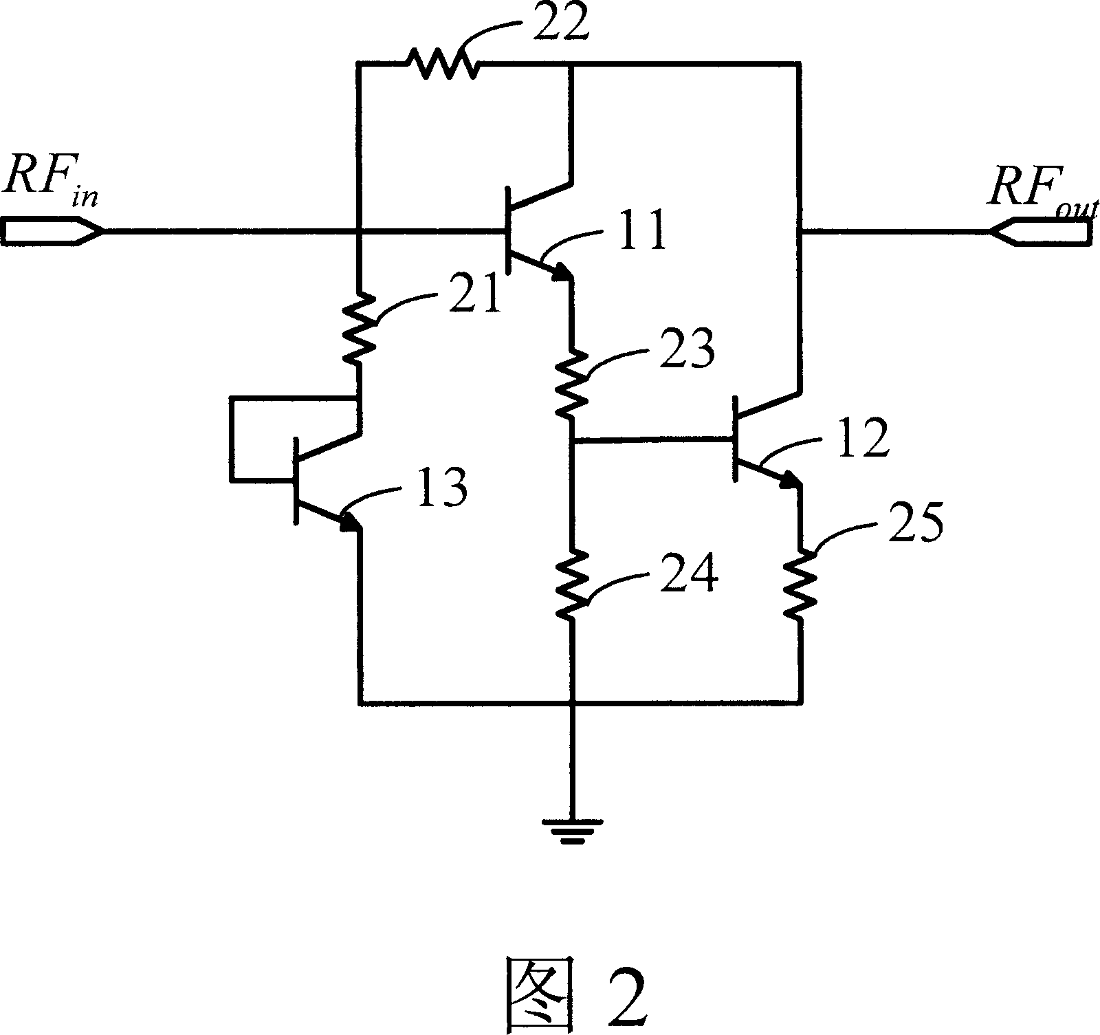
[0029] As shown in Figure 2, Figure 2 is a schematic diagram of a high-gain broadband amplifier circuit with temperature compensation provided by the present invention, which adds an eb structure composed of transistors to a conventional RF broadband amplifier circuit based on a Darlington tube A diode 13, or a diode 13 formed by b and c of transistors connected in parallel to form a eb structure, the circuit includes:

[0030] With the diode 13 connected in series with the voltage dividing resistor 21 in the conventional radio frequency broadband amplifier circuit based on the Darlington tube, the collector of the diode 13 is connected with the conventional radio frequency circuit based on the Darlington tube through the ...


PUM


Abstract

The present invention discloses a high-gain broad-band amplifier circuit that has temperature compensation and consists of a traditional Darlington transistor based routine radio frequency broad band amplifier circuit, a diode 13 that is connected with the dividing resistor 21 in the traditional Darlington transistor based routine radio frequency amplifier circuit, the collector of the diode 13 is connected with the base electrode of the transistor 11 in the traditional Darlington transistor based routine radio frequency broad band amplifier circuit, the collector 13 of the diode 13 is connected with the base electrode of itself, the emitter of the diode 13 is connected with the emitter of the transistor 11 through the dividing resistor 24 and the ballasting resistor 23. The present invention has the advantages of reducing the negative feedback of the amplifier circuit, improving the gain of the amplifier circuit, reducing the changes of the base electrode circuit that are caused by voltage drop changes of the transistor 11 and transistor 12 and gaining the function of compensating the temperature of the circuit.

Description

technical field [0001] The invention relates to the technical field of transistor amplifier circuits, in particular to a high-gain broadband amplifier circuit with temperature compensation. Background technique [0002] In the field of communication technology, high-gain broadband amplifier circuits are widely used in many communication devices. Among them, the conventional radio frequency broadband amplifier circuit based on Darlington tube is the most widely used high-gain broadband amplifier circuit at present. [0003] As shown in FIG. 1 , FIG. 1 is a schematic diagram of a conventional radio frequency broadband amplifier circuit based on a Darlington tube. The amplifier circuit includes a bipolar transistor 11 and a bipolar transistor 12, both of which are connected in series. The input signal from the input RF in input to the base of transistor 11. The base of the transistor 11 is connected to a bias circuit composed of resistors 21 and 22, and the ratio of the res...

Claims


Application Information

Patent Timeline
Patent Type & Authority Applications(China)
IPC IPC(8): H03F1/02H03F1/30H03F1/42
Inventor 王宇晨刘训春
Owner INST OF MICROELECTRONICS CHINESE ACAD OF SCI
Why Eureka
Try Eureka