
CT positioning percutaneously inserting puncture instrument

A percutaneous and bolt-fixing technology, which is applied in the field of CT positioning percutaneous interventional puncture instruments, can solve the problems that it is difficult to obtain consistent coordinate positioning between the image space and the patient space, affect the treatment effect, and the position is not fixed, so as to improve the accuracy of positioning Sex, improve surgical accuracy, and reduce radiation dose

Inactive Publication Date: 2008-02-13
ACCUTARGET MEDIPHARMA (SHANGHAI) CO LTD +1
View PDF0 Cites 29 Cited by
  • Summary
  • Abstract
  • Description
  • Claims
  • Application Information

AI Technical Summary

Problems solved by technology

[0013] In addition, the aforementioned stereotaxic techniques used in neurosurgery are difficult to apply to operations on other parts of the human body. The main reason is that the position of soft tissues in other parts of the human body is not fixed relative to the surrounding bone tissue, making it difficult to achieve a consistent image space and patient space. Coordinate positioning
Therefore, there is no fixed guide and positioning device for interventional puncture in other parts of the human body to fix the direction of puncture. Usually, real-time CT images are used to guide, but because there is no puncture guide and positioning, there is still blindness in the puncture process. There is no objective and accurate position mark for the puncture instrument, and it is difficult to fix the puncture needle on the predetermined trajectory during the puncture process. It can only be based on the doctor's personal experience, and the direction needs to be constantly adjusted by image scanning. The final result may still be different from the ideal planned route. There is a certain offset, and it is time-consuming and affects the treatment effect

Method used


Image

  • CT positioning percutaneously inserting puncture instrument
  • CT positioning percutaneously inserting puncture instrument
  • CT positioning percutaneously inserting puncture instrument

Examples


Embodiment Construction

[0030] The present invention will be further described below in conjunction with the accompanying drawings and specific embodiments.

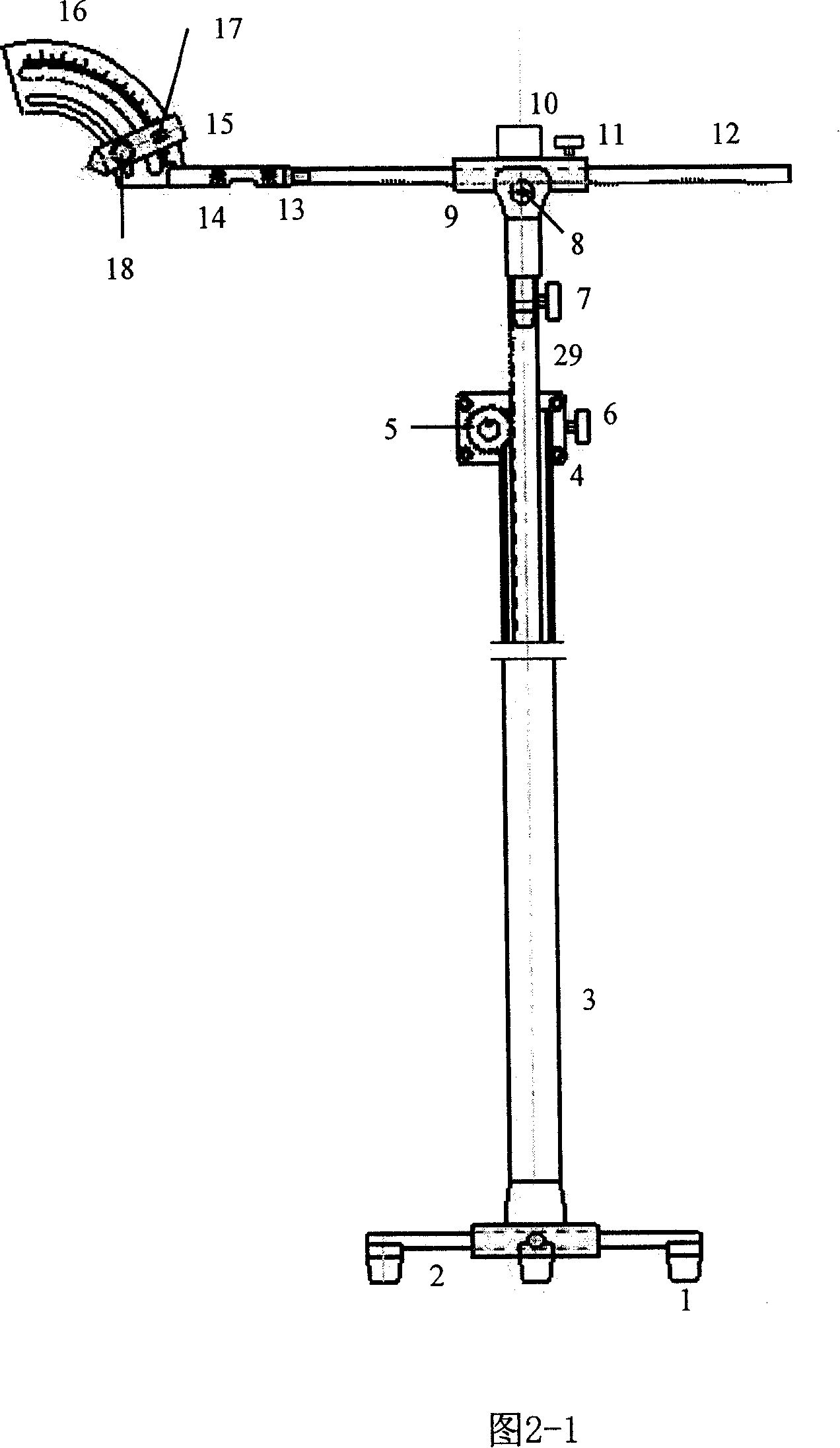
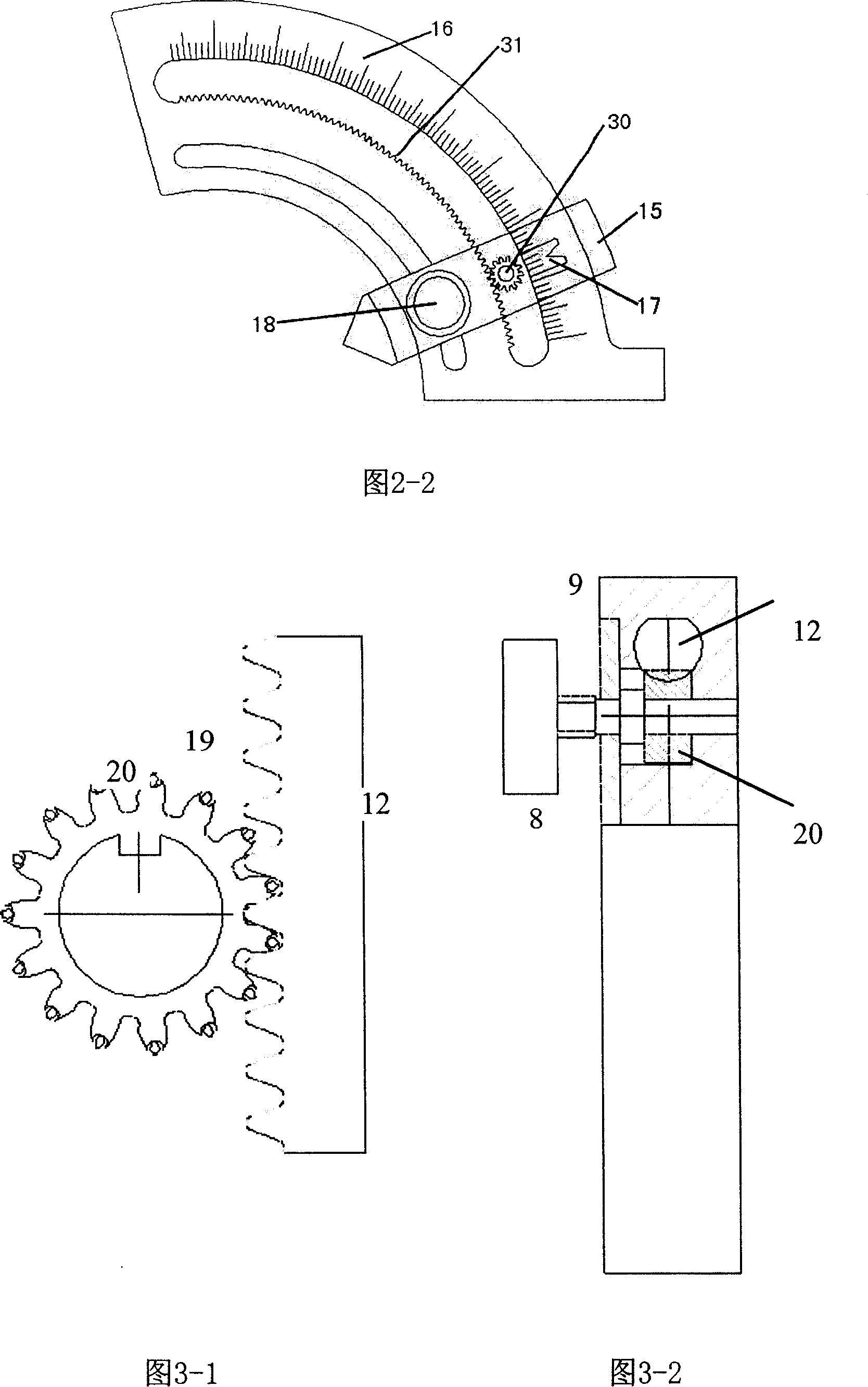
[0031] As shown in Figures 2-1 and 5, a CT positioning percutaneous interventional puncture instrument proposed by a preferred embodiment of the present invention includes a frame and a crossbar 12 that can be adjusted in height and horizontal position, and the crossbar 12 Installed on the height adjustment rod 29 of the frame body through the lock nut 7, the cross bar 12 is provided with an angle plate 16, the angle plate 16 is provided with a position pointer 15, and the position pointer 15 is provided with a puncture guide fixing device installation hole 28 The puncture guide fixing device comprises a fixed block 26, a fixed bolt 24, a bolt sleeve 25 and a puncture guide installation hole 18, the fixed block 26 and the fixed bolt 24 are welded as one, and the bolt sleeve 25 is enclosed within the fixed bolt 24, and the fixed A puncture guide...


PUM


Abstract

The present invention discloses a percutaneous interventional puncture instrument through CT positioning, which is used in the guiding positioning of puncture needle in CT-guided percutaneous interventional surgery or other percutaneous interventional instrument. The device comprises a frame body and a cross bar fixed in the frame body. The cross bar is provided with an angular disk, which is provided with a position pointer. A hole is arranged in the position pointer. The fixing device for the puncture guiding device comprises a fixed block, a fixed bolt, a bolt sleeve and the fixing hole of the puncture guiding device arranged in the sleeve tube. The fixing device for the puncture guiding device is arranged in the hole of position pointer. The present invention is used in guiding positioning of needle in the targeted surgery or other percutaneous interventional instrument. Besides targeted interventional therapy for tumor, the present invention can be used in the treatment process of all CT guided percutaneous punctures requiring fixing needle or other percutaneous interventional instrument in a certain direction.

Description

technical field [0001] The invention is a CT positioning percutaneous interventional puncture instrument, which is used for guiding and positioning a puncture needle or other percutaneously inserted instruments in percutaneous interventional operations. Background technique [0002] A large number of clinical data show that: 70-80% of tumor patients are already in the advanced stage when they are diagnosed, and lose the chance of surgical resection. Traditional radiotherapy and chemotherapy are limited by dosage, so it is difficult to completely inactivate tumor cells, and the therapeutic effect is not satisfactory. In recent years, the development of new targeted ablation therapy technologies such as laser, freezing, radiofrequency, microwave and other physical ablation methods has changed the traditional concept of tumor treatment. Targeted therapy is to deliver a therapeutic probe to the tumor site through percutaneous puncture, and perform ablation therapy on the tumor ...

Claims


Application Information

Patent Timeline
IPC IPC(8): A61B6/03A61B17/00
Inventor 戴海雄武清
Owner ACCUTARGET MEDIPHARMA (SHANGHAI) CO LTD
Learn More