Two-stage rotating wheel dehumidification air conditioner device capable of using low-grade heat source

A low-grade heat source and wheel dehumidification technology, applied in household heating, air-conditioning systems, applications, etc., can solve problems such as complex structure, inability to remove moisture, difficulties, etc., to meet comfort requirements, significant emission reduction effect, easy The effect of control

Inactive Publication Date: 2008-02-13
SHANGHAI JIAO TONG UNIV
View PDF1 Cites 29 Cited by
  • Summary
  • Abstract
  • Description
  • Claims
  • Application Information

AI Technical Summary

Problems solved by technology

[0003] Conventional single-wheel dehumidification has the following disadvantages: 1) The regeneration temperature is high, mainly using heat sources such as electric heat and steam, and it is difficult to apply low-grade heat sources such as solar energy and waste heat
2) The dehumidification capacity is limited, and sufficient moisture cannot be removed. Without the cooperation of electric refrigeration, the air supply temperature and humidit...

Method used


Image

  • Two-stage rotating wheel dehumidification air conditioner device capable of using low-grade heat source
  • Two-stage rotating wheel dehumidification air conditioner device capable of using low-grade heat source

Examples


Embodiment 1

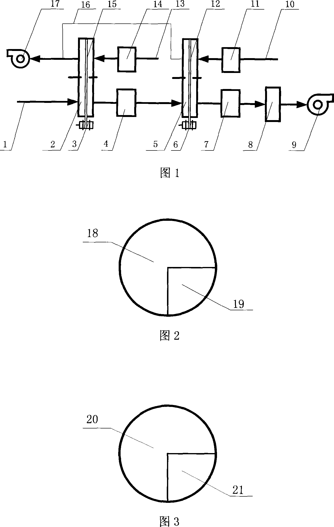
[0032] The structure of this embodiment is shown in Figure 1, and this embodiment includes: a processing air inlet duct 1, a first-stage dehumidification runner 2, a first-stage dehumidification runner drive motor 3, a first-stage treatment heat exchanger 4, and a first-stage dehumidification runner drive motor 3. Second-stage dehumidification rotor 5, second-stage dehumidification rotor drive motor 6, second-stage treatment heat exchanger 7, evaporative cooler 8, treatment fan 9, second-stage regenerative air inlet duct 10, second-stage regenerative heating Device 11, second-stage dehumidification runner drive belt 12, first-stage regeneration air inlet duct 13, first-stage regeneration heater 14, first-stage dehumidification runner drive belt 15, second-stage regeneration air outlet duct 16 , regeneration fan 17.

[0033] As shown in Figure 2, the first stage dehumidification rotor 2 treatment area 18 and the regeneration area 19 account for 3 / 4 and 1 / 4 of the area of ​​...

Embodiment 2

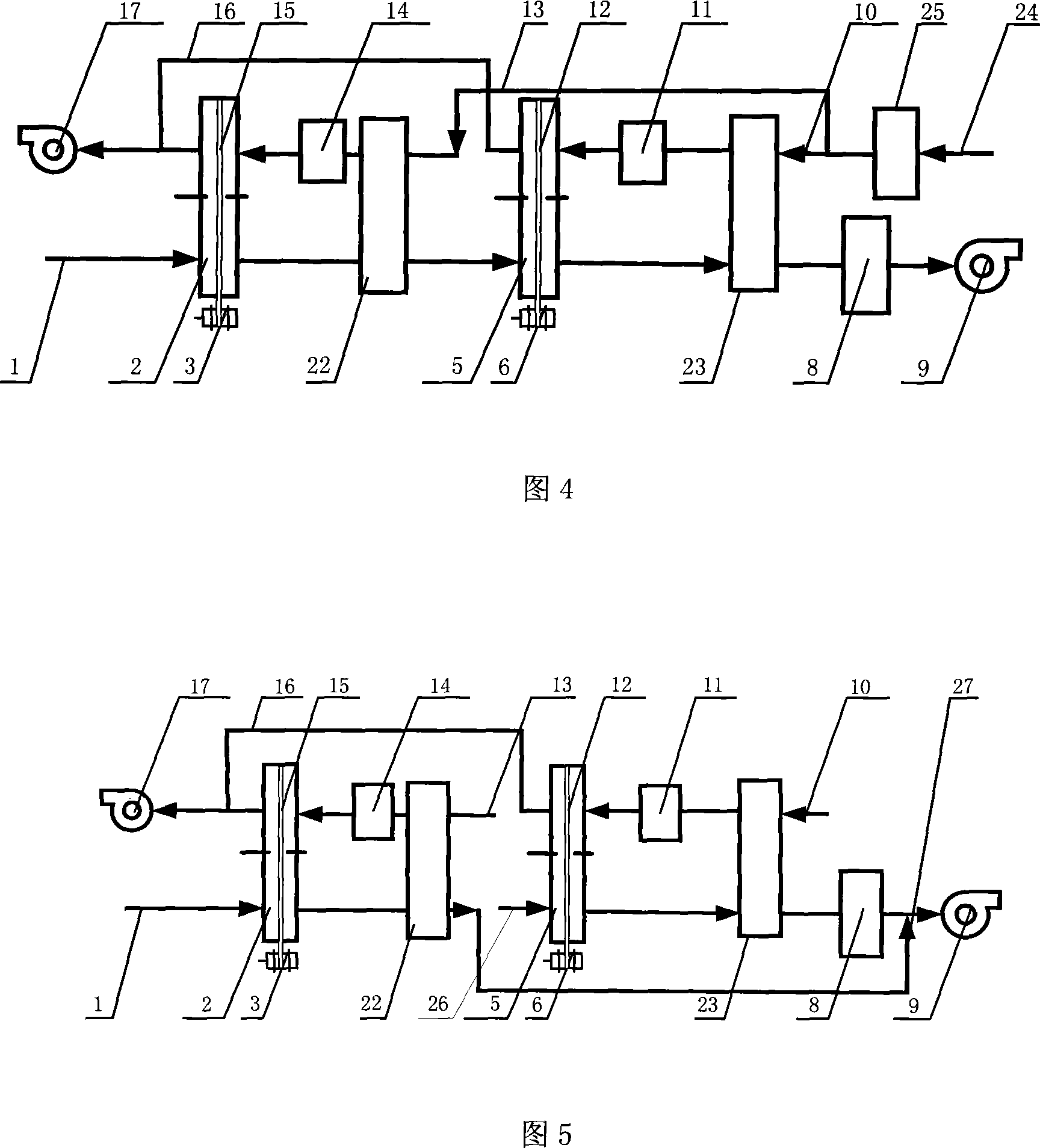
[0044] The structure of this embodiment is shown in Figure 4. The two-stage rotor dehumidification air conditioner includes: a processing air inlet duct 1, a first-stage dehumidification runner 2, a first-stage dehumidification runner drive motor 3, and a first-stage processing circuit. Heater 22, second-stage dehumidification runner 5, second-stage dehumidification runner drive motor 6, second-stage treatment regenerator 23, evaporative cooler 8, treatment fan 9, second-stage regeneration air inlet duct 10, Second-stage regenerative heater 11, second-stage dehumidification runner drive belt 12, first-stage regeneration air inlet duct 13, first-stage regeneration heater 14, first-stage dehumidification runner drive belt 15, second-stage regeneration Air outlet duct 16, regeneration fan 17, regeneration air inlet main pipe 24, regeneration side evaporative cooler 25. Figure 2 and Figure 3 are schematic diagrams of the first-stage dehumidification rotor 2 and the second-stage de...

Embodiment 3

[0054] The structural form of this embodiment is shown in FIG. 5 . Compared with Example 2, the structure of this embodiment has no evaporative cooler on the regeneration side and is only used for heating in winter.

[0055] Compared with Embodiment 2, the difference in its connection method is:

[0056] The treatment air passes through the treatment side outlet of the first-stage treatment regenerator 22 and is connected with the treatment blower 9 through the air duct 27 . The second-stage treatment air inlet pipe 26 is connected to the air inlet side of the treatment area of ​​the second-stage dehumidification rotor 5, and the air outlet side of the treatment area of ​​the second-stage dehumidification rotor 5 is treated with the second-stage treatment regenerator 23 through the air duct. The side inlets are connected, and the second-stage treatment regenerator 23 is connected to the evaporative cooler 8 through an air pipe. The evaporative cooler 8 is connected with the ...


PUM


Abstract

A two grade runner dehumidification air-conditioning device, which belongs to refrigeration dehumidification technical field and can make use of low grade heat source, includes two stage dehumidification runners, two stage heat exchanges, two heaters, an evaporative cooler, a treating fan, a regeneration fan, a motor and a belt or a gear. The motor is connected with the dehumidification runners through the belt or the gear and drives the dehumidification runners to rotate. Every dehumidification runner is equipped with two areas of a treating area and a regeneration area. The treating area of the first stage dehumidification runner is connected with the inlet of the first stage heat exchanger. The outlet of the first stage heat exchanger is connected with the treating area of the second stage dehumidification runner. The other side of the second stage dehumidification runner is connected with the second stage heat exchanger. The second stage heat exchange is connected with the evaporative cooler. The evaporative cooler is connected with the treating fan. The regeneration fan is respectively connected with the regeneration areas of the two stage dehumidification runners. Two heaters are respectively connected with the other sides of the regeneration areas of the two stage dehumidification runners. Enough temperature and humidity descending can be achieved by the invention without an electric refrigeration air conditioning.

Description

technical field [0001] The invention relates to an air conditioner in the technical field of refrigeration, in particular to a two-stage desiccant dehumidification air conditioner capable of utilizing low-grade heat sources. Background technique [0002] The rotary dehumidification technology using low-grade heat source is in line with the current general trend of energy saving, emission reduction and sustainable development. The dehumidification of the solid rotor can use a low-grade heat source to drive the drying rotor to remove the moisture in the air, making it into dry air, and then achieve the required temperature and humidity range through direct evaporative cooling, which can slow down the tense trend of power supply. In addition, the dehumidification of the rotary wheel reduces the use of chlorofluorocarbon refrigerants, and there is no CFCS problem and no greenhouse effect. It is an environmentally friendly refrigeration method. The latest research also found tha...

Claims


Application Information

Patent Timeline
IPC IPC(8): F24F3/14
Inventor 代彦军李勇王如竹翟小强吴静怡葛天舒
Owner SHANGHAI JIAO TONG UNIV
Why Eureka
Try Eureka