
Gradient coil system and magnetic resonance chromatography X-ray camera

一种梯度线圈、X射线的技术,应用在梯度线圈系统领域,能够解决梯度线圈系统不能使用等问题,达到制造成本低、成本有利、运行成本低的效果

Active Publication Date: 2008-02-13
SIEMENS HEALTHCARE GMBH
View PDF4 Cites 9 Cited by
  • Summary
  • Abstract
  • Description
  • Claims
  • Application Information

AI Technical Summary

Problems solved by technology

So as long as there is only one hole in a cooling channel, the entire gradient coil system cannot be used

Method used


Image

  • Gradient coil system and magnetic resonance chromatography X-ray camera
  • Gradient coil system and magnetic resonance chromatography X-ray camera
  • Gradient coil system and magnetic resonance chromatography X-ray camera

Examples


Embodiment Construction

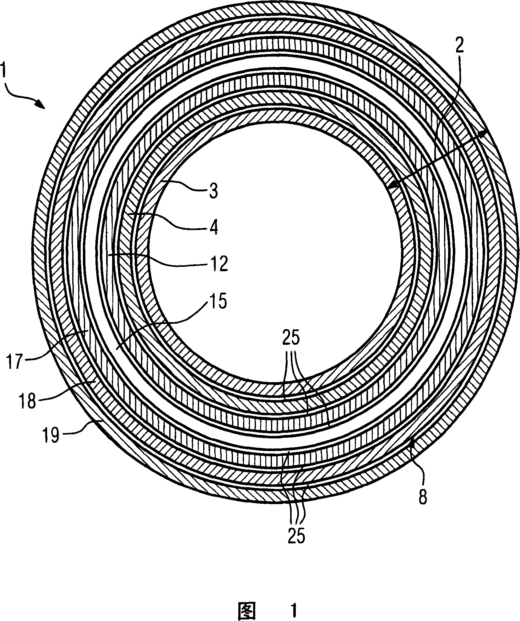
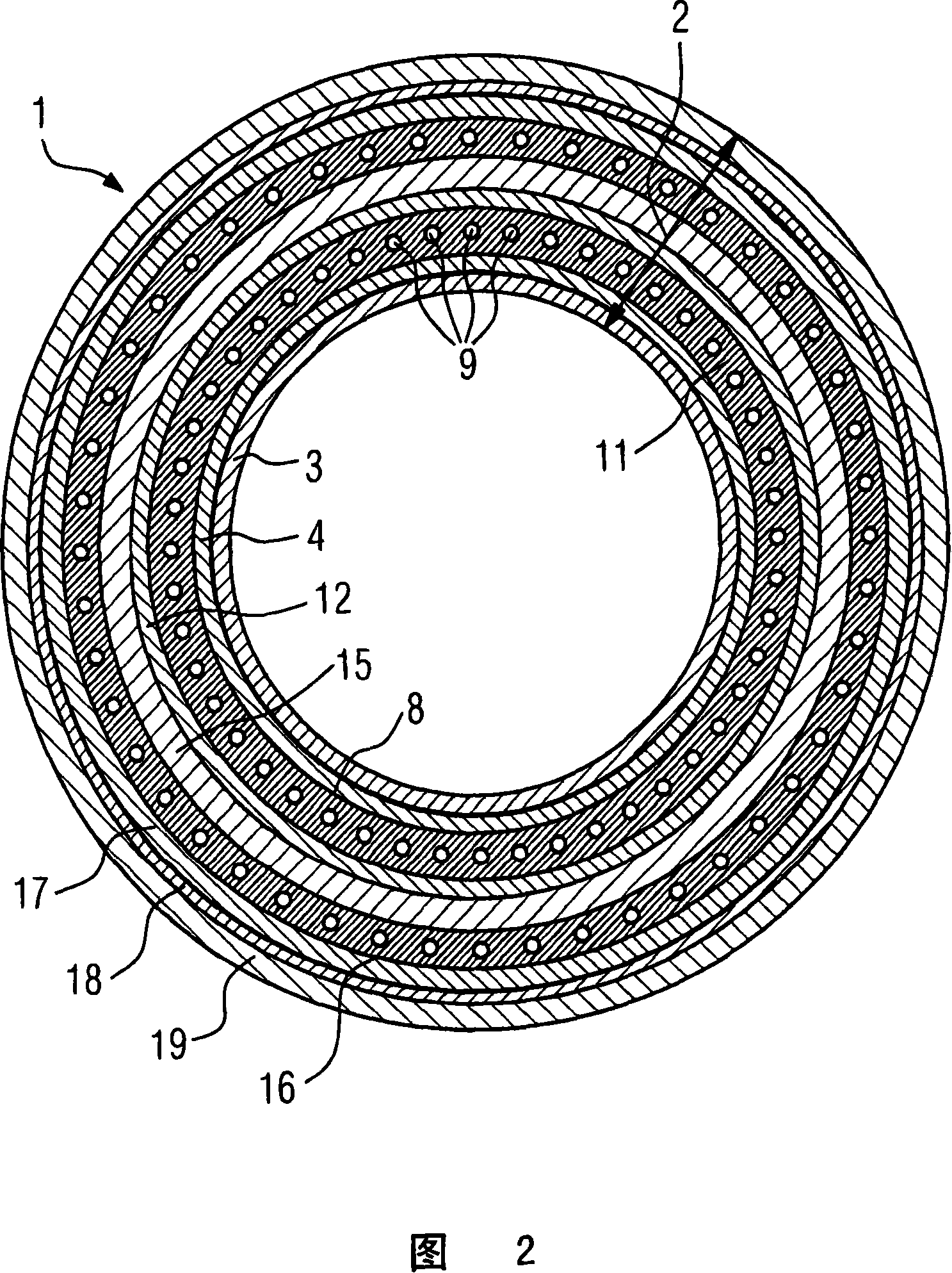
[0034]FIG. 2 shows a gradient coil system 1 according to the prior art. This gradient coil system 1 has a concentrically arranged layer structure 2 of the hollow cylinder type. The installation of the individual layers of the layer structure is done from inside to outside in radial direction. The first hollow cylindrical layer is mounted on the housing surface of a cylindrical mounting aid. The second layer is mounted on the outer shell surface of the first layer, and so on.

[0035] The innermost two layers are a first gradient coil layer 3 and a second gradient coil layer 4 for respectively generating a transverse gradient magnetic field. The gradient coils used in the two gradient coil layers 3 , 4 are saddle coils.

[0036] The next next layer is a first cooling layer 8 . In this case, this is a cooling duct 9 which is arranged in a meander on the outer surface of the second gradient coil layer 4 and serves to dissipate the heat generated by the gradient coil layer. T...


PUM


Abstract

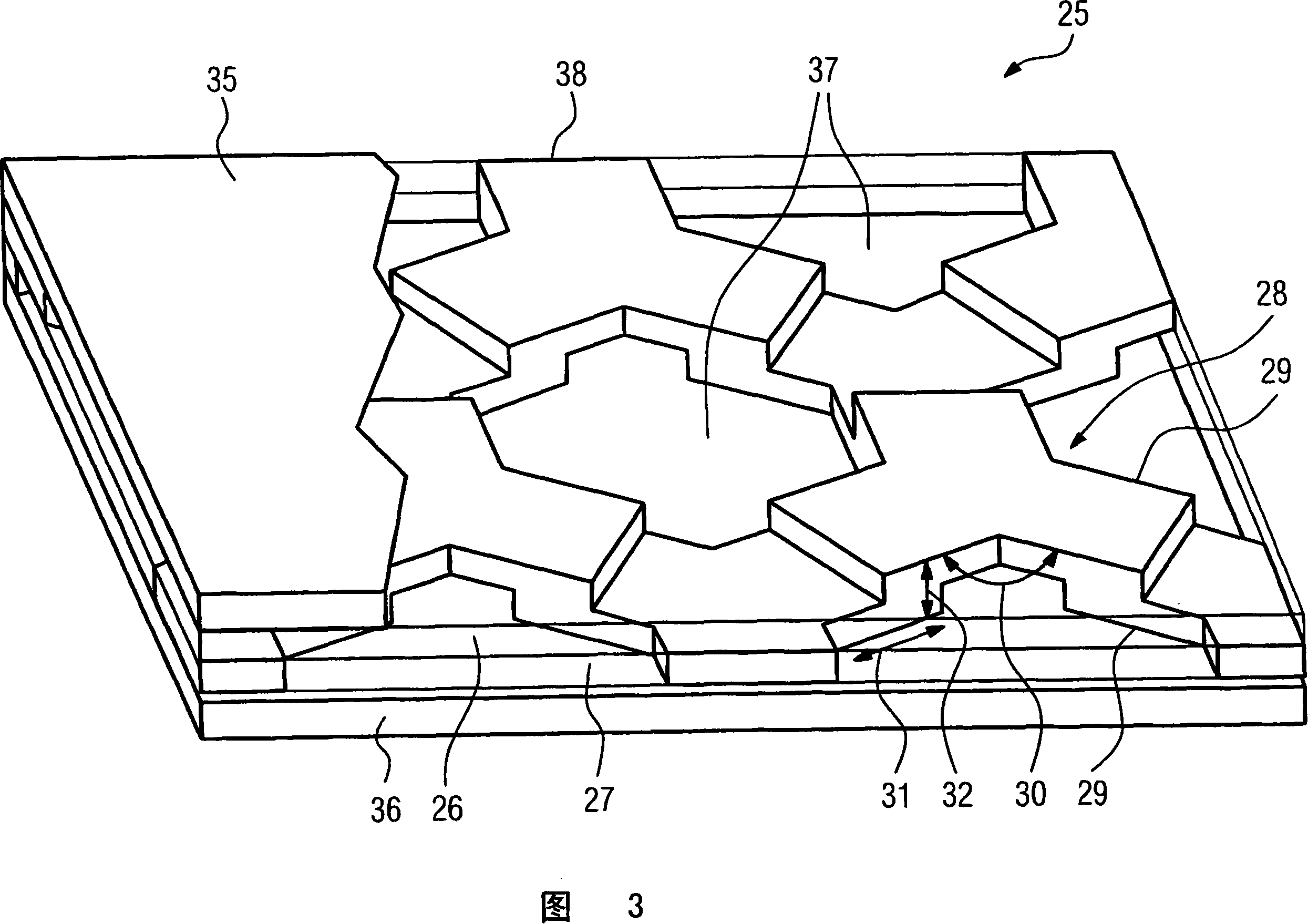
A gradient coil system for a magnetic resonance tomography apparatus has a layer structure including a gradient coil layer and a cooling layer. The cooling layer is fashioned as a plate heat exchanger, composed of plates, for cooling the gradient coil layer. In this way, a highly efficient cooling of the gradient coil layer is achieved with a lower structural height compared to conventional tubular configurations.

Description

technical field [0001] The invention relates to a gradient coil system, in particular for a magnetic resonance tomograph. The gradient coil system has a layer structure comprising a gradient coil layer and a cooling layer. Background technique [0002] During the operation of the magnetic resonance tomography camera, at least one gradient magnetic field and one fundamental magnetic field must coincide in order to generate images. This is produced by means of a gradient coil system. Usually the gradient coil system has several gradient coil layers with one or more gradient coils in order to generate three vertically overlapping gradient fields. In actively shielded gradient coil systems used today, in addition to the gradient coil layer generating the effective field, further gradient coil layers are provided which shield the effective field from the outside. These additional gradient coil layers are arranged around the gradient coil layers generating the effective field a...

Claims


Application Information

Patent Timeline
Patent Type & Authority Applications(China)
IPC IPC(8): G01R33/385
CPCH01F27/2876F28D9/0087F28D9/0012F28F21/065F28F3/086H01F27/10G01R33/3856
Inventor B·格罗万尔N·胡伯J·书斯特L·肖恩S·斯托克
Owner SIEMENS HEALTHCARE GMBH
Learn More