
Filling method of contact hole

A filling method and technology for contact holes, which are applied in electrical components, semiconductor/solid-state device manufacturing, circuits, etc., can solve the problems of large contact hole resistance, poor uniformity, and high contact hole resistance, and reduce contact resistance. value, improve filling quality, improve the effect of electrical characteristics

Active Publication Date: 2008-03-12
SEMICON MFG INT (SHANGHAI) CORP +1
View PDF1 Cites 28 Cited by
  • Summary
  • Abstract
  • Description
  • Claims
  • Application Information

AI Technical Summary

Problems solved by technology

[0007] The above filling method is currently the most commonly used contact hole filling method, but the contact hole filled by this method still has a problem of high resistance value, because the low resistance TiSi formed at the bottom of the contact hole x There is also a high-resistance TiN layer between the metal tungsten and the metal tungsten, which still leads to a large resistance value of the contact hole
[0008] The Chinese patent application number 200410067835.5 discloses a method for depositing a tungsten plug barrier layer when filling a contact hole. This method uses a Ti / TiN layer with a certain thickness as the barrier layer of the tungsten plug, which improves the contact hole and the underlying metal layer. The problem of high contact hole resistance and poor uniformity caused by line dislocations
However, this method does not do any treatment to the high-resistance TiN with a thickness of 200 to 300 Ȧ, and does not improve the problem of high resistance of the contact hole caused by the existence of TiN, and cannot further reduce the resistance of the contact hole. Improve electrical characteristics of contact holes

Method used


Image

  • Filling method of contact hole
  • Filling method of contact hole
  • Filling method of contact hole

Examples


Embodiment Construction

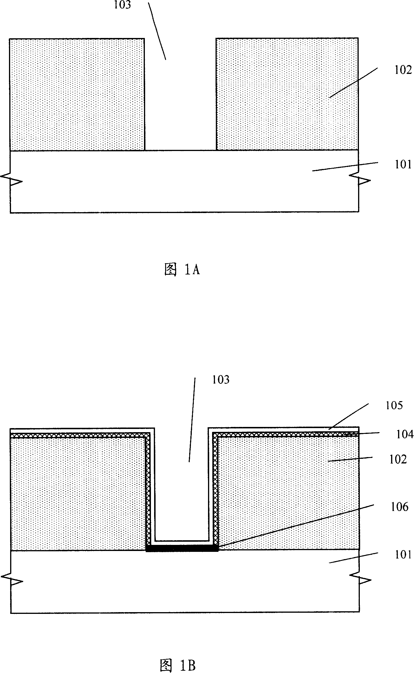
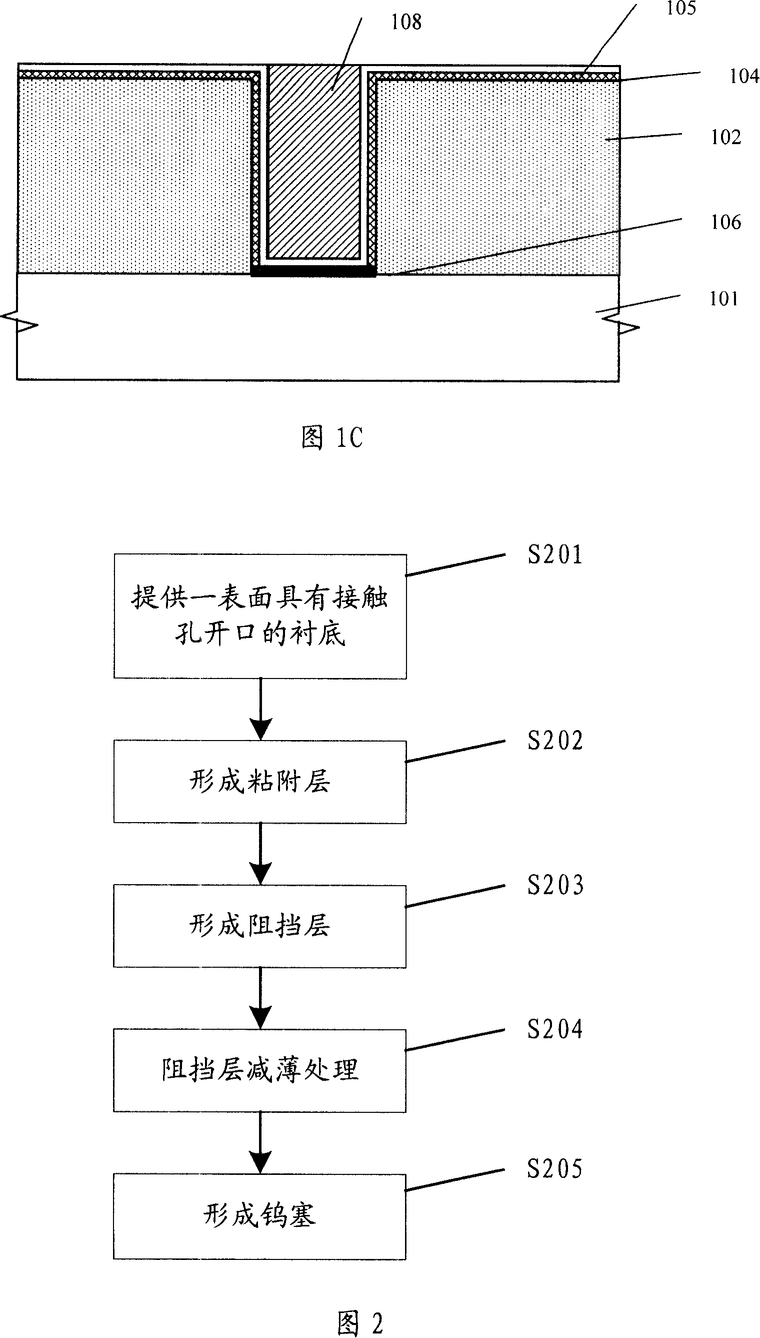
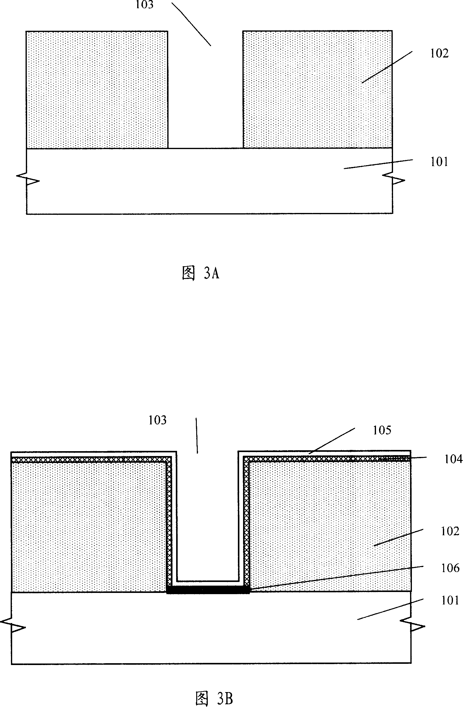
[0028] In order to make the above objects, features and advantages of the present invention more comprehensible, specific implementations of the present invention will be described in detail below in conjunction with the accompanying drawings.

[0029] The processing method of the present invention can be widely applied in many applications, and can utilize many suitable materials to make, and below is to illustrate by preferred embodiment, certainly the present invention is not limited to this specific embodiment, this field Common replacements known to those skilled in the art undoubtedly fall within the protection scope of the present invention.

[0030] Secondly, the present invention is described in detail using schematic diagrams. When describing the embodiments of the present invention in detail, for the convenience of explanation, the cross-sectional view showing the semiconductor structure will not be partially enlarged according to the general scale, which should not ...


PUM


Abstract

A padding method for contact hole is provided, which comprises: providing an underlay with at least one open mouth on its surface; forming the adhesion layer on the said underlay; forming the barrier layer on the said adhesion layer; reduction processing to the said barrier layer at bottom of the open mouth of the contact hole; forming W-Plug inside the said open mouth of the contact hole. The padding method in the invention reduces the thickness of the barrier layer at bottom of the contact hole and improves the electrical properties of the contact hole.

Description

technical field [0001] The invention relates to the technical field of semiconductor manufacturing, in particular to a method for filling a contact hole. Background technique [0002] As the production of integrated circuits develops towards ultra-large-scale integrated circuits (ULSI), the internal circuit density is getting larger and larger, and the number of components contained is increasing, making the surface of the wafer unable to provide enough area to make the required interconnection ( Interconnect). Therefore, in order to meet the increased demand for interconnection lines after component shrinkage, the design of multilayer metal interconnection lines with more than two layers has become a necessary method for VLSI technology. At present, the conduction between different metal layers is achieved by digging an opening in the insulating layer between the two metal layers and filling it with a conductive material to form a contact hole structure that conducts the t...

Claims


Application Information

Patent Timeline
Patent Type & Authority Applications(China)
IPC IPC(8): H01L21/768
Inventor 朱旋宋伟基毛刚何德飚
Owner SEMICON MFG INT (SHANGHAI) CORP
Learn More