Electronic ballast
An electronic ballast and voltage technology, applied in electric light sources, electrical components, lighting devices, etc., can solve the problems of many links and low efficiency, and achieve the effect of simple circuit and high efficiency
- Summary
- Abstract
- Description
- Claims
- Application Information
AI Technical Summary
Problems solved by technology
Method used
Image

Examples
Embodiment Construction
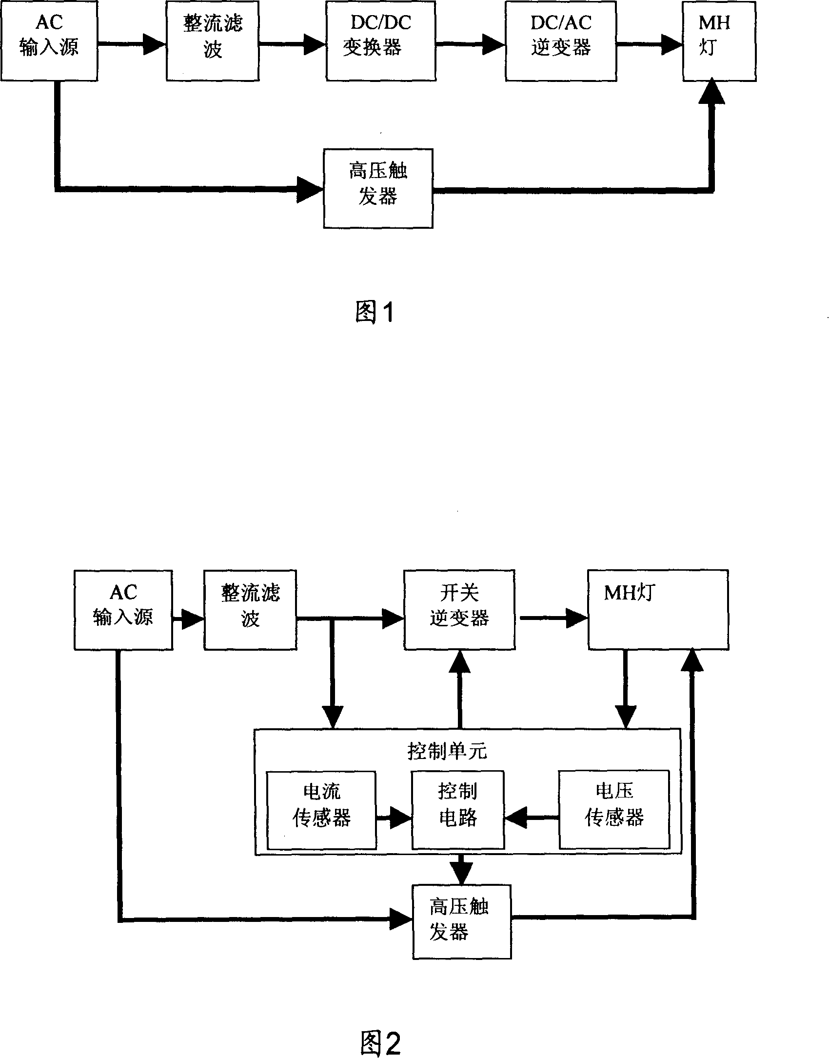
[0056] A preferred embodiment of the present invention is shown in Figure 2, which includes a rectification and filtering circuit for rectifying and filtering ordinary AC power; a high-voltage trigger for providing a high-voltage trigger signal for load R0 at startup, and switching inverter and control unit,
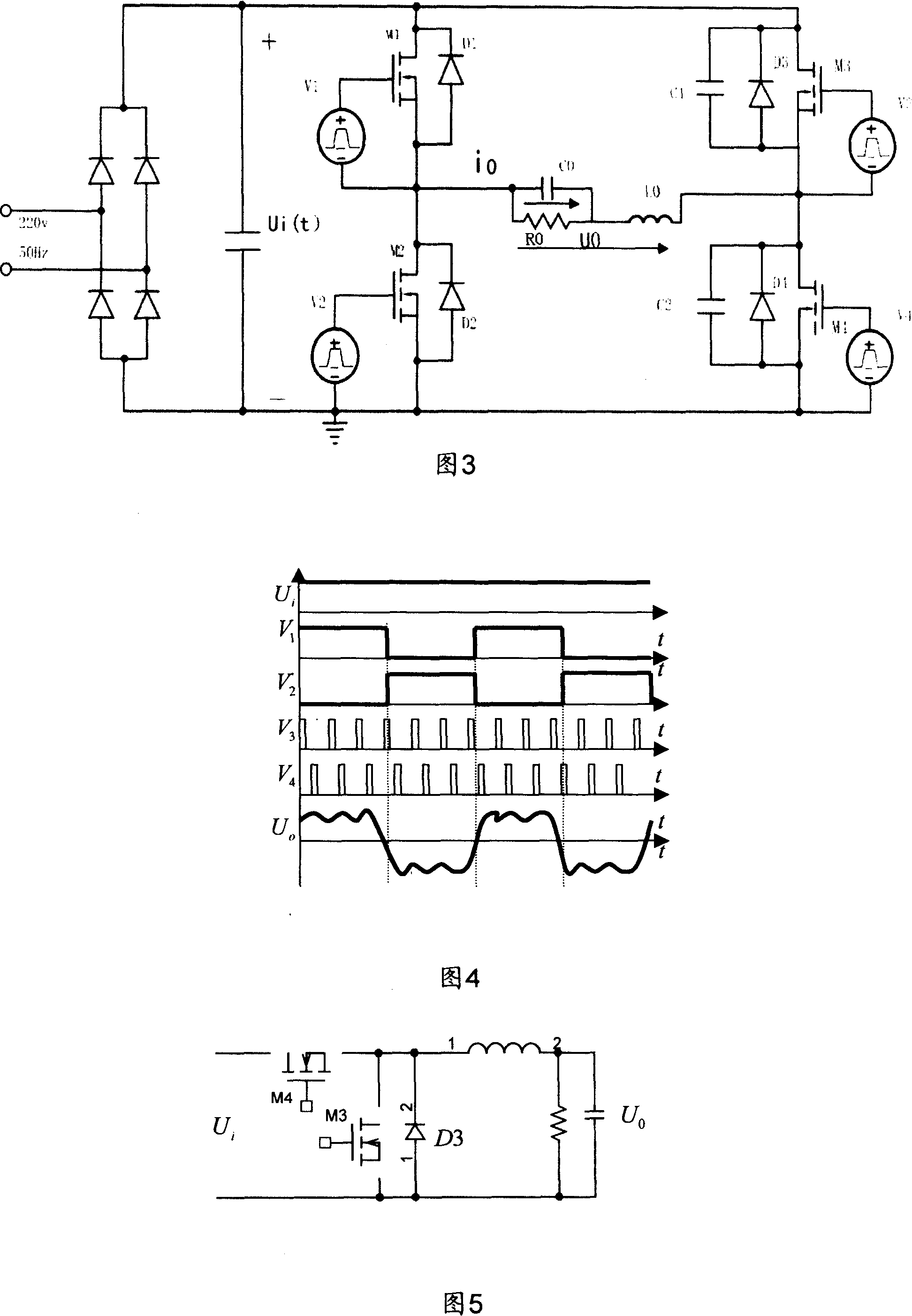
[0057]The switching inverter receives the DC output from the rectification and filtering circuit, and converts the received DC power into a voltage and current that matches the electrical characteristics of the load R0, and then converts the DC power into a medium and low frequency square wave signal for driving the load R0 The operation; the load R0 here is mainly for MH (metal halide) lamps, and can also be other purely resistive loads, inductive loads, and loads in various applications where the output frequency is industrial frequency.
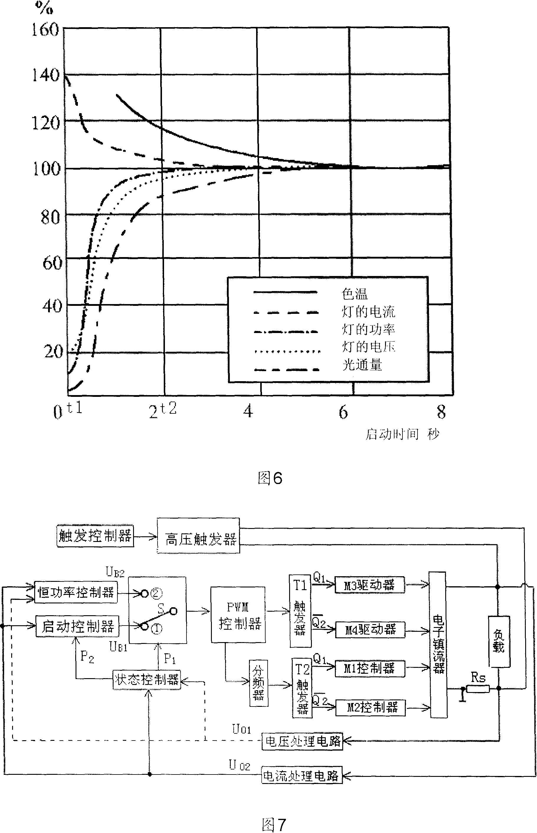
[0058] The control unit is used to control the operation of the electronic ballast. The start and operation of the MH lamp is cont...
PUM
 Abstract
Description
Claims
Application Information
 - Generate Ideas
- Intellectual Property
- Life Sciences
- Materials
- Tech Scout
- Unparalleled Data Quality
- Higher Quality Content
- 60% Fewer Hallucinations
Browse by: Latest US Patents, China's latest patents, Technical Efficacy Thesaurus, Application Domain, Technology Topic, Popular Technical Reports.
© 2025 PatSnap. All rights reserved.Legal|Privacy policy|Modern Slavery Act Transparency Statement|Sitemap|About US| Contact US: help@patsnap.com