Control method for interleaved dual-tube positive excitation converter

A control method and dual-tube forward excitation technology, which can be used in control/regulation systems, output power conversion devices, and conversion equipment with intermediate conversion to AC, which can solve problems such as reverse recovery loss

Inactive Publication Date: 2008-03-19
DELTA ELECTRONICS INC
View PDF2 Cites 10 Cited by
  • Summary
  • Abstract
  • Description
  • Claims
  • Application Information

AI Technical Summary

Problems solved by technology

[0018] However, the disadvantage of the control method in Fig. 5 is that when the freewheeling diodes D1 and D3 on the primary side flow through the load

Method used


Image

  • Control method for interleaved dual-tube positive excitation converter
  • Control method for interleaved dual-tube positive excitation converter
  • Control method for interleaved dual-tube positive excitation converter

Examples


Embodiment Construction

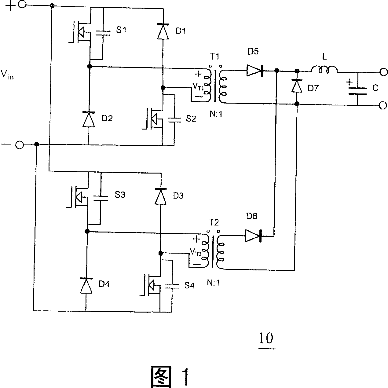
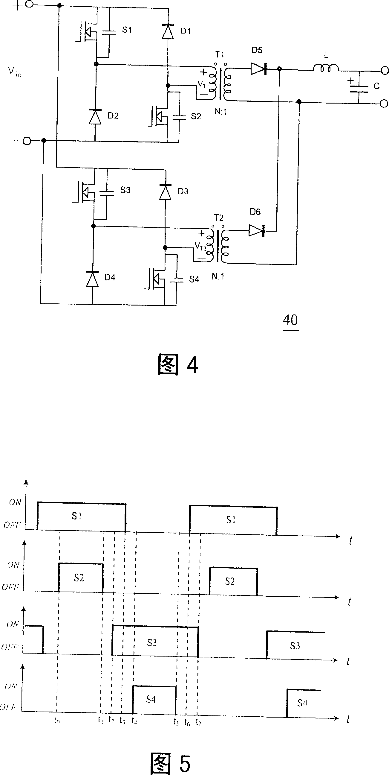
[0128] The control method of the present invention can be applied to the interleaved two-transistor forward converter 10 or 40 of FIG. 1 or FIG. repeat.

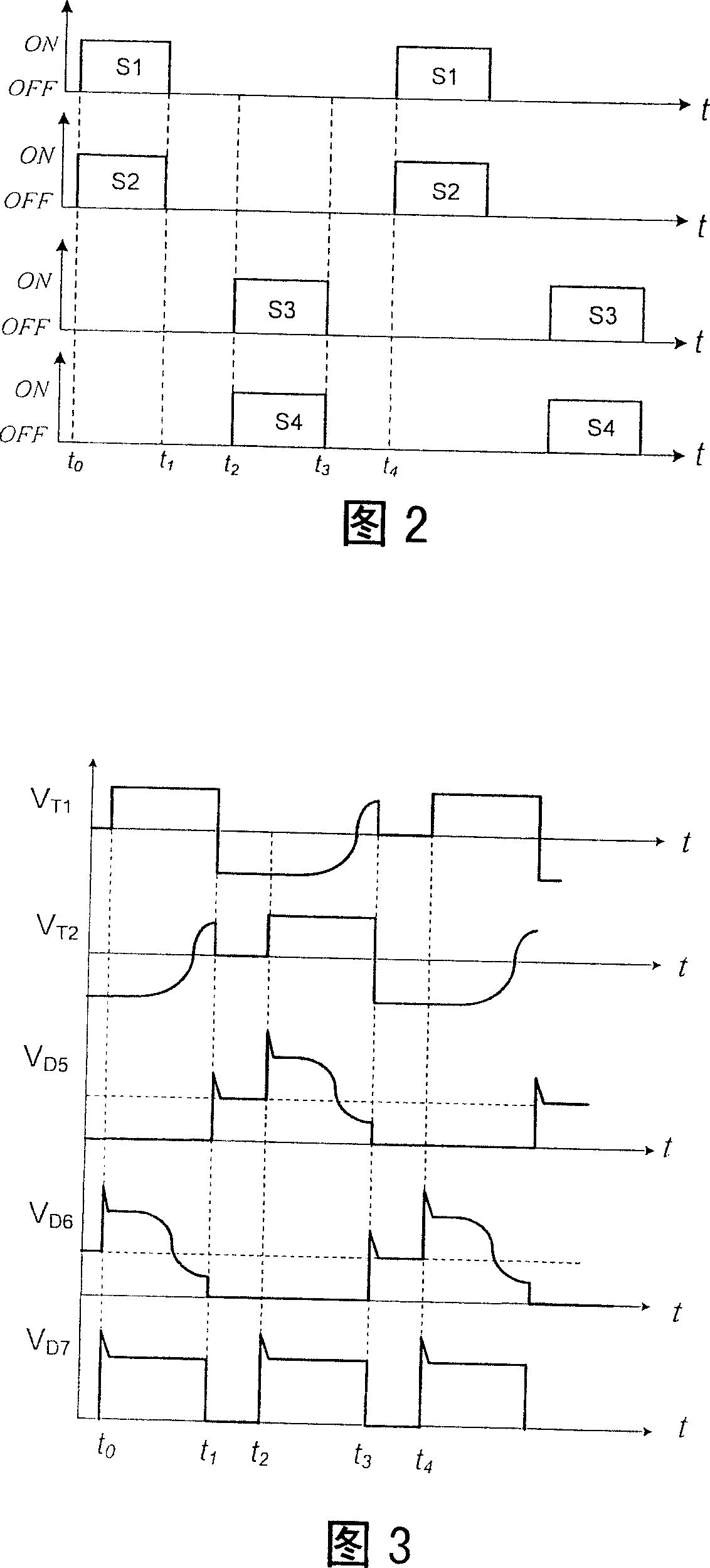
[0129] Please refer to Fig. 6, which is a timing diagram when using the control method proposed by the present invention to control each transistor switch of the interleaved two-transistor forward converter of Fig. 1 or Fig. 4, wherein the horizontal axis is time, and the vertical axis is The ON / OFF state of each transistor switch. It can be seen from Fig. 6 that the difference between the control method of the present invention and the aforementioned two traditional control methods is that the switches S1 and S2 are turned on at the same time, but they are not turned off at the same time, but the switch S2 is turned off after the switch S3 is turned on; Similarly, the switches S3 and S4 are turned on at the same time, but not turned off at the same time. Instead, the switch S4 is turned off after the switch S1 is turned on...


PUM


Abstract

The invention provides a controlling method for a staggering duplex tube forward converter. The converter comprises two main change-over circuits that are connected with each other in parallel; and each main change-over circuit comprises a first power semiconductor switch, a second power semiconductor switch, a first diode, a second diode, a transformer, and a rectification switch. The controlling method comprises that the paired power semiconductor switches are switched on simultaneously but not simultaneously switched off, instead, the second power semiconductor switch in the other pair is not switched off until the first and the second power semiconductor switches in one pair are switched on.

Description

technical field [0001] The invention relates to a control method of an interleaved double-tube forward converter, in particular to an interleaved double-tube forward converter applied to a power supply. Background technique [0002] With the rapid development of power supply technology, the market has put forward higher requirements for the efficiency (including the efficiency at full load and light load), reliability, and power density of server power supplies and communication power supplies. Among the various converters, the interleaved two-transistor forward converter has been widely used due to its many advantages; Switching at half the input voltage results in lower switching losses, a symmetrical architecture results in lower electromagnetic interference (EMI) noise, and the equivalent frequency on the secondary side of the transformer is twice that of the primary side to reduce its secondary side The volume of the connected filter inductor, etc. [0003] Please ref...

Claims


Application Information

Patent Timeline
IPC IPC(8): H02M3/28H02M3/335
Inventor 应建平吴洪洋陈潇曾剑鸿
Owner DELTA ELECTRONICS INC
Why Eureka
Try Eureka