
Fast recovery diode and its preparation method

A recovery diode, N-type technology, applied in the field of diodes, can solve the problem of high forward conduction voltage drop, achieve the effects of reducing forward conduction voltage drop, reducing reverse recovery time, and reducing loss

Active Publication Date: 2022-01-28
GREE ELECTRIC APPLIANCES INC
View PDF9 Cites 0 Cited by
  • Summary
  • Abstract
  • Description
  • Claims
  • Application Information

AI Technical Summary

Problems solved by technology

[0003] The purpose of the present invention is to provide a fast recovery diode and its preparation method to solve the problem in the prior art that using a higher platinum expansion temperature to reduce the reverse recovery time of the fast recovery diode can easily lead to a higher forward conduction voltage drop

Method used


Image

  • Fast recovery diode and its preparation method
  • Fast recovery diode and its preparation method

Examples


Embodiment Construction

[0035] In order to make the purpose, technical solutions and advantages of the embodiments of the present invention clearer, the technical solutions in the embodiments of the present invention will be clearly and completely described below in conjunction with the drawings in the embodiments of the present invention. Obviously, the described embodiments It is a part of embodiments of the present invention, but not all embodiments. Based on the embodiments of the present invention, all other embodiments obtained by persons of ordinary skill in the art without making creative efforts belong to the protection scope of the present invention.

[0036] It should be noted that in the present invention, unless otherwise specified, all the implementation modes and preferred implementation methods mentioned herein can be combined with each other to form a new technical solution. In the present invention, if there is no special description, all the technical features and preferred feature...


PUM

PropertyMeasurementUnit
thicknessaaaaaaaaaa
electrical resistivityaaaaaaaaaa
thicknessaaaaaaaaaa

Abstract

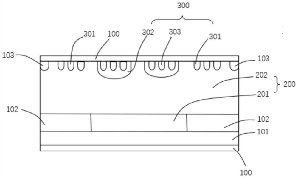
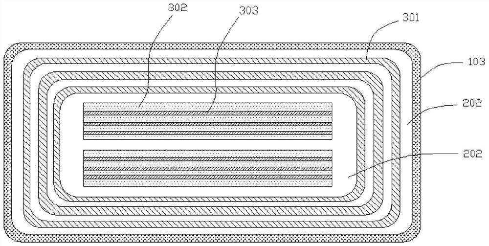
The invention provides a fast recovery diode and relates to the field of diodes. The fast recovery diode includes: a substrate layer; an N-type epitaxial layer located on the surface of the substrate layer; a P-type injection region located on the surface of the substrate layer and arranged on the side of the N-type epitaxial layer; a diffusion region, It is located in the top region of the N-type epitaxial layer and is separated from the P-type implantation region. The use of the fast recovery diode can solve the problem of high forward conduction voltage drop when the reverse recovery time of the fast recovery diode is reduced by the platinum expansion process in the prior art. By changing the structure of the fast recovery diode, the reverse recovery time of the fast recovery diode can be reduced. purpose of recovery time.

Description

technical field [0001] The invention relates to the technical field of diodes, in particular to a fast recovery diode and a preparation method thereof. Background technique [0002] Fast recovery diode (FRD: fast recovery diode) is a semiconductor diode with switching characteristics and short reverse recovery time. It is mainly used in electronic circuits such as switching power supplies, PWM pulse width modulation, and inverters, as high-frequency rectifier diodes, continued flow diodes are used. The loss generated during the operation of the fast recovery diode mainly comes from dynamic loss and forward conduction loss. The current mainstream technology uses the method of platinum expansion and electron irradiation to control the carrier lifetime to reduce the reverse recovery time of the fast recovery diode. Thereby reducing its dynamic loss. At present, when using the platinum expansion process to reduce the reverse recovery time of the diode, usually in order to obta...

Claims


Application Information

Patent Timeline
Patent Type & Authority Patents(China)
IPC IPC(8): H01L29/861H01L29/06H01L21/329
CPCH01L29/861H01L29/0603H01L29/0619H01L29/66136
Inventor 刘勇强曾丹敖利波肖婷史波
Owner GREE ELECTRIC APPLIANCES INC
Learn More