Numerically controlled machine tool vehicle processing parts rod material automatic feeding method and device
A CNC machine tool and automatic feeding technology, which is applied in metal processing equipment, automatic/semi-automatic lathes, turning equipment, etc., can solve the problems of complex structure and inapplicable CNC lathe transformation, improve the working environment, reduce the incidence of equipment failure, reliable performance
- Summary
- Abstract
- Description
- Claims
- Application Information
AI Technical Summary
Problems solved by technology
Method used
Image

Examples
Embodiment 1
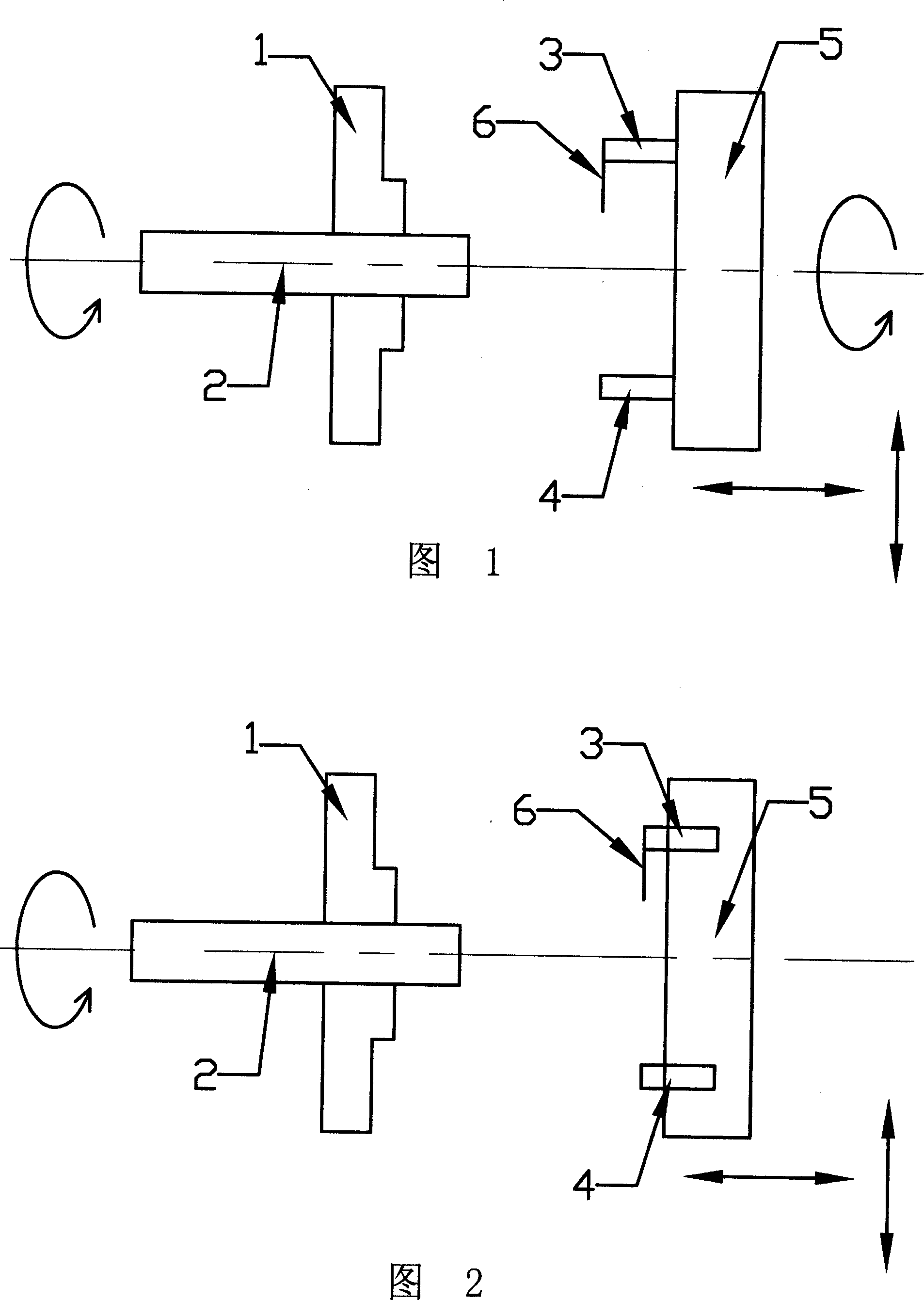
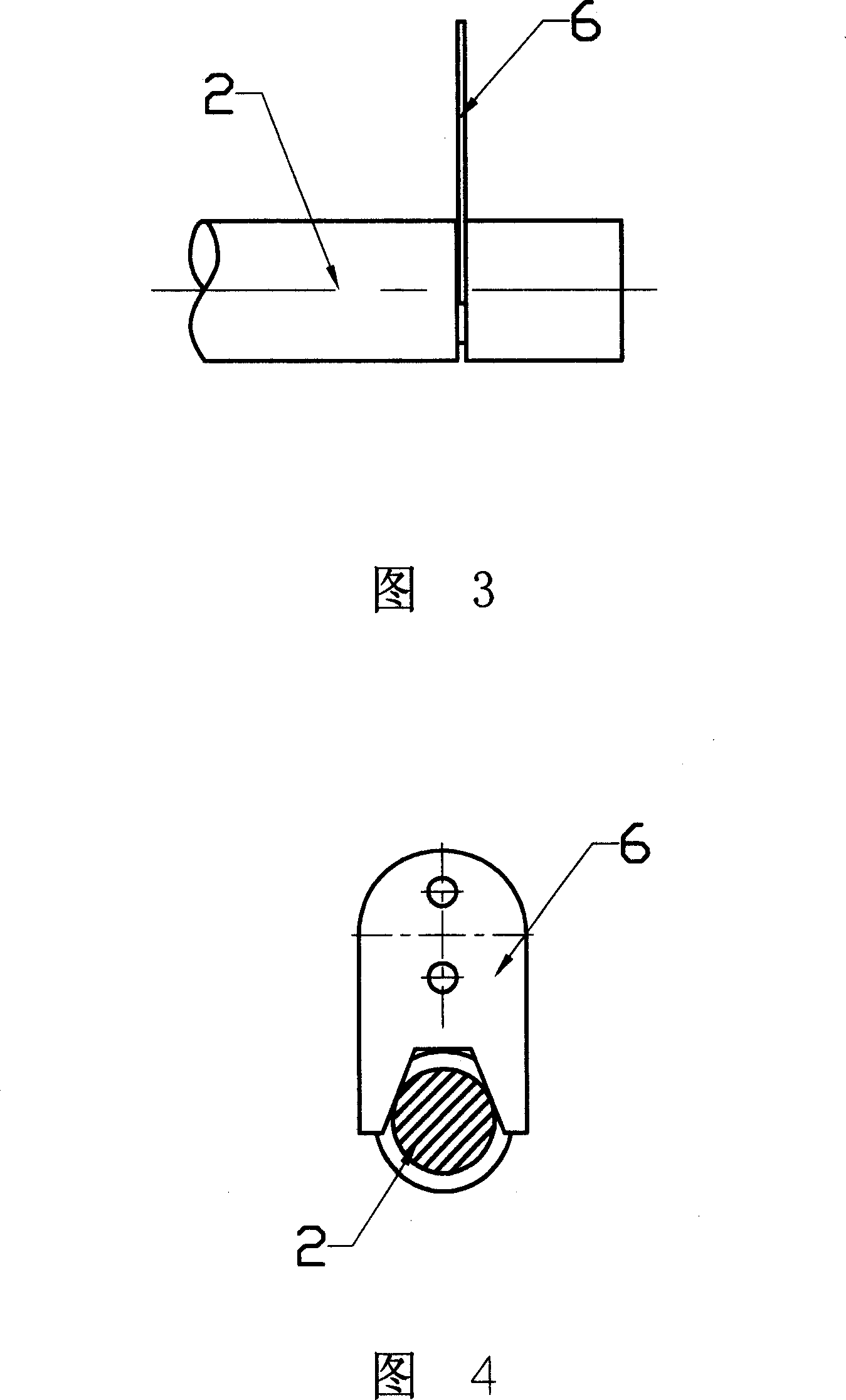
[0024] Embodiment 1: Referring to Figures 1, 3, and 4, processing tools 4 are respectively arranged on the CNC rotary turret 5, and a pulling jig 6 with a "Y" fork opening is fixed by a fixed block 3, wherein the opening is aligned with the machine tool The axis is vertical, the thickness of the clamp is 3mm, and the opening is at an angle of 30-80°. After the parts are processed, move the tool forward to the position to be cut off, process a shallow ring groove, rotate and move the turret, make the pulling jig radially snap into the processing shallow groove (Figure 3, 4), and release the 2 clamps of the bar material Holder 1, retract the turret in the axial direction and pull out the material at a fixed length, lock the bar material holder 1, move the turret to radially withdraw from the jig, turn the turret, and cut the processed parts according to the processing slot, according to the original setting The program machines the next part. The above-mentioned fixed-length dr...
Embodiment 2
[0025] Embodiment 2: Referring to Figures 2, 3, and 4, as in Embodiment 1, a machining tool 4 and a pulling fixture 6 are respectively provided on the numerically controlled knife row turret 5 . After the parts are processed, move the turret to cut off the processed parts, move the turret, and process a shallow ring groove at the place where the next part has a radial machining allowance, and move the turret to make the pulling clamp radially snap into the processing Shallow slot (Fig. 3, 4), loosen bar 2 holder 1, move the turret axially to pull out the material at a fixed length, lock the bar holder 1, move the turret to radially exit the fixture, move the turret , process the next part according to the original setting program. The above-mentioned fixed-length drawing process is realized by compiling a macro program separately and setting the calling program in the original program.
Embodiment 3
[0026] Embodiment 3: Add a pulling jig 6 with a U opening on the turret 5 . After the parts are processed, move the turret so that the pulling jig radially snaps into the upper step of the part, loosen the bar holder, move the turret axially to pull out the material at a fixed length, lock the bar holder, and move the knife The turret exits the jig radially, moves the turret, cuts off the processed parts, moves the turret, and processes the next part according to the original setting program. The turret can be the rotary turret in Embodiment 1, or the row-type turret in Embodiment 2, and the movement of the turret is determined according to the form of the turret.
[0027] In addition, the drawing bar can also be set on the turret, such as a spring-type collet, through the clamp-type drawing.
PUM
| Property | Measurement | Unit |
|---|---|---|
| Thickness | aaaaa | aaaaa |
Abstract
Description
Claims
Application Information
 - R&D
- Intellectual Property
- Life Sciences
- Materials
- Tech Scout
- Unparalleled Data Quality
- Higher Quality Content
- 60% Fewer Hallucinations
Browse by: Latest US Patents, China's latest patents, Technical Efficacy Thesaurus, Application Domain, Technology Topic, Popular Technical Reports.
© 2025 PatSnap. All rights reserved.Legal|Privacy policy|Modern Slavery Act Transparency Statement|Sitemap|About US| Contact US: help@patsnap.com