Compressed air engine electrically driven whole-variable valve actuating system

An electric drive and compressed air technology, which is applied to engine components, variable displacement engines, machines/engines, etc., can solve the problems of large liquid inertia force, high machining accuracy, and complex structure of the electro-hydraulic variable valve system, and achieve structural Simple, achieve recycling, low energy consumption

Inactive Publication Date: 2008-03-26
ZHEJIANG UNIV
View PDF2 Cites 54 Cited by
  • Summary
  • Abstract
  • Description
  • Claims
  • Application Information

AI Technical Summary

Problems solved by technology

However, the electro-hydraulic variable valve system has the disadvantages of obvious changes due to the influence of temperature, large inertial force of the liquid, and large energy consumption.
The working principle of the electric drive method is roughly the same as that of the electro-hydraulic drive method, except that the working medium is replaced by compressed air. Compared with the electro-hydraulic drive, the compressed...

Method used


Image

  • Compressed air engine electrically driven whole-variable valve actuating system

Examples


Embodiment Construction

[0015] The present invention will be described in detail below in conjunction with the accompanying drawings.

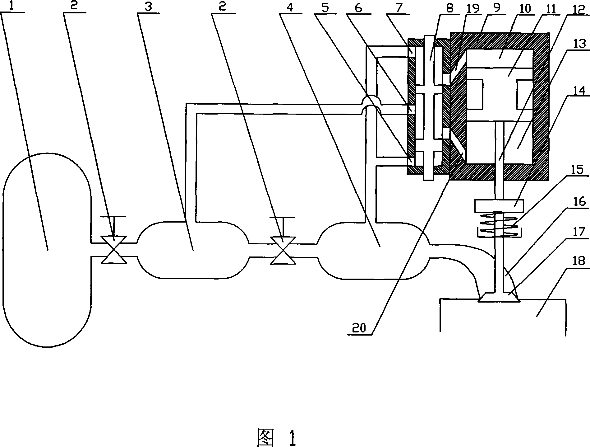
[0016] In the present embodiment, the electrically driven full variable valve drive system of the compressed air engine is shown in Figure 1, comprising a high-pressure gas storage tank 1, a pressure-stabilizing tank 4 (secondary decompression gas tank) and a valve 17 positioned on a cylinder 18, stabilizing The pressure box 4 is connected to the cylinder 18 through the intake manifold 16, and the valve 17 is connected to the valve spring 15, the coupling 14, the piston rod 12 and the piston 11 in sequence, so the opening and closing movement of the valve 17 is through the reciprocating movement of the piston 11. exercise to achieve.

[0017] The piston 11 is located in the control cylinder 9, and divides the inner chamber of the control cylinder 9 into an upper working chamber 10 and a lower working chamber 13, and the upper working chamber 10 and the lower working ...


PUM


Abstract

The present invention relates to compressed air engine, and is especially one kind of variable air valve driving system for compressed air engine. The system includes one air valve spring, one shaft coupler, one piston rod and one piston inside a cylinder, connected successively to the air valve. There are two communication states between the air passage and the air exhaust electromagnetic directional valve based on the final position of the valve. The valve opening time may be controlled by means of controlling the power-on pulse duration. The present invention has the advantages of capacity of decoupling air valve motion and the crankshaft rotation speed of the pneumatic engine to optimize the air distributing phase, capacity of recovering the vehicle braking energy, convenient braking strength regulation, etc.

Description

technical field [0001] The invention relates to a compressed air engine device, more specifically, the invention relates to a fully variable valve drive system of the compressed air engine. Background technique [0002] The continuous soaring of fuel prices and the increasing environmental pollution caused by fuel vehicles have made countries all over the world step up the research and development of new energy vehicles. The pneumatic engine uses compressed air and liquid nitrogen as the working medium, does not need to consume oil during the work process, and can achieve zero emissions, which is a development direction. The main power source of the compressed air engine comes from the compressed air entering the cylinder, and its load is mainly realized by adjusting the amount of air entering the cylinder. The control of the intake air volume can be completed by adjusting the intake pressure and the intake time. However, the throttle control method is used to adjust the i...

Claims


Application Information

Patent Timeline
IPC IPC(8): F01L9/02F01L13/00F01B3/10F01L9/10F01L9/40
Inventor 陈平录俞小莉沈瑜铭刘林聂相虹胡军强
Owner ZHEJIANG UNIV
Why Eureka
Try Eureka