Non-metal reinforcement member

A non-metallic reinforcement and reinforcement technology, applied in electrical components, conductors, insulated cables, etc., can solve the problems of increasing the outer diameter of the optical cable, increasing the consumption of optical cable materials, etc., to ensure tensile performance, weight reduction, and cost reduction. Effect

Inactive Publication Date: 2008-03-26
龚建良
View PDF0 Cites 8 Cited by
  • Summary
  • Abstract
  • Description
  • Claims
  • Application Information

AI Technical Summary

Problems solved by technology

[0002] In the prior art, non-metallic optical cables usually use rigid cylindrical FRP (glass fiber reinforced plastics) and non-metallic reinforcement strips as their reinforcements. With the continuous development of the business, therefore, it is required that the optical cable can bear enough tensile force, so that the optical cable can be used on the adjacent iron tower or pole of the specified span. Due to the current limitation of the tensile modulus of FRP, for this reason, the optical cable Manufacturers have to increase the size of the reinforcement, or add additional reinforcement layers such as external fibers and fangluns outside the cable core, so that the outer diameter of the cable is virtually increased, and the material consumption of the cable is increased.

Method used


Image

  • Non-metal reinforcement member

Examples


Embodiment 1

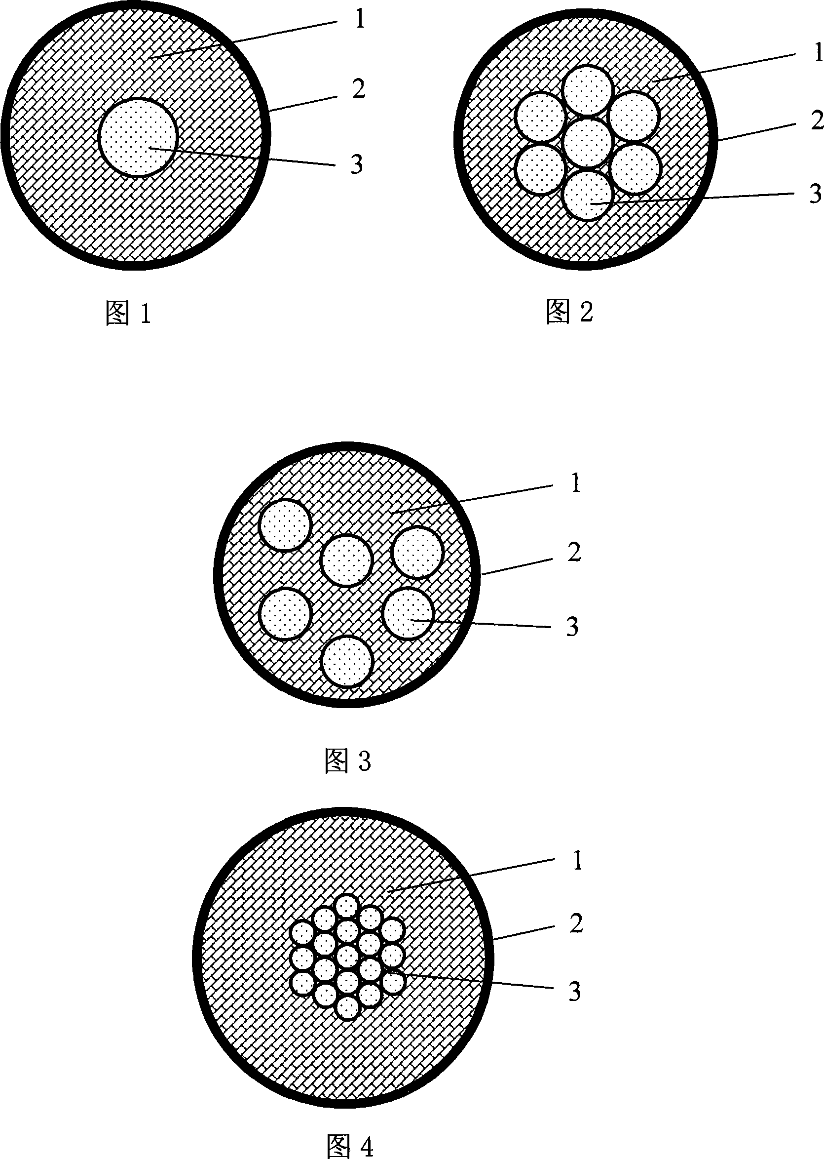
[0019] See Figure 1 for details. In the figure, 1 is the bonding layer, 2 is the extruded layer, and 3 is the high-strength yarn. Among them, the high-strength yarn 3 and the bonding layer 1 are distributed in the extruded layer 2, the high-strength yarn 3 is distributed between the bonding layers 1, the cross-section of the entire reinforcing member is circular, and the high-strength yarn 3 adopts a single-strand aromatic Lun yarn, the outer diameter of which is 0.3mm, the thickness of the extruded layer is 0.85mm, and the outer diameter of the entire reinforcement is 2.0mm. Adhesive layer 1 is made of 0.3mm-2.1mm long glass fiber, adhesive and hot melt adhesive; the adhesive is synthetic resin type, the material of extruded layer 2 is natural color medium density polyethylene, high-strength yarn 3 Located in the center of extruded layer 2.

[0020] Of course, the bonding layer 1 can be bonded by 0.001mm-5mm long glass fibers, adhesives, and hot-melt adhesives; adhesives, ac...

Embodiment 2

[0027] Referring to Fig. 2 for details, it is basically the same as embodiment 1, except that the high-strength yarn 3 in this embodiment is twisted into an aramid rope by 7 shares of aramid yarn, and its strength is higher.

Embodiment 3

[0029] Referring to Fig. 3 for details, it is basically the same as embodiment 1, except that the high-strength yarn 3 in this embodiment is dispersed and distributed in the extrusion layer 2 by 6 strands of glass fiber filaments, and its strength is higher.

[0030] Of course, if there are 2 or more glass fiber filaments, aramid yarns, PBO (poly-p-phenylene benzobisoxazole fibers) or the above two or more mixed yarns distributed in the extruded layer 2, it is also possible Should be the protection scope of the present invention.


PUM

PropertyMeasurementUnit
thicknessaaaaaaaaaa

Abstract

This invention relates to a kind of nonmetal reinforcement, it is composed of high strength gauze, the felt layer and the plastic layer. The high strength gauze and the felt layer are in the plastic layer, the high strength gauze is between the felt layer, the cross section of the reinforcement is circle or ellipse, the thickness of the plastic layer is 0.2mm-120mm, the high strength gauze is the line or net has at least one section of fiber glass, aryl gauze, PBO (Poly-para-benzoquinone benzodiazole) or at least one fiber glass, aryl gauze, PBO (Poly-para-benzoquinone benzodiazole). This invention can reach the high stretch-proof request to the nonmetal optical fiber cable in exist technology in the situation that not increase even reduce the size of exist optical fiber cable, so it can save the cost of optical fiber cable, save the space, solves the idea that people want to solve but never gain success.

Description

technical field [0001] The invention relates to a strengthening material for optical cables, in particular to a non-metallic strengthening member for optical cables. Background technique [0002] In the prior art, non-metallic optical cables usually use rigid cylindrical FRP (glass fiber reinforced plastics) and non-metallic reinforcement strips as their reinforcements. With the continuous development of the business, therefore, it is required that the optical cable can bear enough tensile force, so that the optical cable can be used on the adjacent iron tower or pole of the specified span. Due to the current limitation of the tensile modulus of FRP, for this reason, the optical cable Manufacturers have to increase the size of the reinforcement, or add additional reinforcement layers such as external fibers and aramids outside the core of the optical cable. In this way, the outer diameter of the optical cable is virtually increased, and the material consumption of the optica...

Claims


Application Information

Patent Timeline
Patent Type & Authority Applications(China)
IPC IPC(8): G02B6/44H01B11/22H01B7/17
Inventor 龚建良
Owner 龚建良
Why Eureka
Try Eureka