Multi-chip light emitting diode module group structure and method of producing the same

A technology of light-emitting diode and module structure, which is applied in semiconductor/solid-state device manufacturing, electrical components, electric solid-state devices, etc., to solve the problem of centralized heat dissipation and improve the effect of integration

Active Publication Date: 2010-05-12
APT ELECTRONICS
View PDF4 Cites 0 Cited by
  • Summary
  • Abstract
  • Description
  • Claims
  • Application Information

AI Technical Summary

Problems solved by technology

However, at present, people have not yet applied the advantages of the flip-chip structure to the manufacture and packaging of multi-color chip light-emitting diode chip modules. Design and manufacturing methods for new high-power LED products

Method used


Image

  • Multi-chip light emitting diode module group structure and method of producing the same
  • Multi-chip light emitting diode module group structure and method of producing the same
  • Multi-chip light emitting diode module group structure and method of producing the same

Examples


Embodiment 1

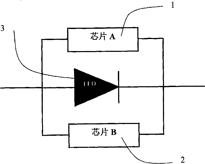
[0046] The circuit structure design of the multi-chip light-emitting diode module according to the present embodiment is as follows: figure 1 As shown, the module includes a voltage and current control integrated circuit chip 1, an antistatic integrated circuit chip 2 and a light-emitting diode chip 3. Among them, the chip 1 and the light-emitting diode LED chip 3 are connected in series, and can be adjusted according to the needs of the light-emitting diode LED chip. , Control the voltage on the LED chip and the passing current to realize different light-emitting modes of multi-chip and multi-color LED modules, such as flashing, color changing, gradually brightening, gradually dimming and other light-emitting modes. Chip 2 is an anti-static integrated A circuit chip, which is connected in parallel with the LED chip 3, to protect the LED chip from being damaged during high-voltage electrostatic discharge.

[0047] Although there is only one LED chip in this embodiment, those s...

Embodiment 2

[0060] In this embodiment, aluminum nitride co-sintered ceramics (A1N) are used as the bottom plate material, and the integration of red, green and blue LED chips combined with the mounting of voltage and current control chips and antistatic chips is taken as an example and described with reference to the accompanying drawings.

[0061] Figure 7a It is a cross-sectional view of the AlN base plate 5, on which the corresponding metal circuits have been laid out according to the requirements of the red, green and blue LED chips 3a, 3b, 3c, current and voltage control chip 1 and anti-static chip 2, and the same LED chip and anti-static chip have been prepared. Chip 2 corresponds to metal bump 4 . Figure 7b It is a sectional view of a module integrating chip 1 and chip 2 and red, green and blue LED chips 3a, 3b, 3c. Figure 7c It is a top view of the multi-chip LED module.


PUM


Abstract

The invention discloses a multi-chip LED module structure and a method for manufacturing the same, wherein, the module comprises at least one LED chip wherein, the metal electrode layers on a P-regionand an N-region are provided with flip-chip bonding metal bumps; at least an integrated circuit control chip such as a current control chip, a voltage control chip and static-free chip; a bedplate for flip-chip bonding which is provided with a metal line layer which connects the LED chip and the integrated circuit control chip and with bumps for flip-chip which are corresponding to the metal bumps on the LED chip, wherein, the LED chip is bonded on the bedplate by flip-chip bonding; the control chip is arranged on the bedplate or in the bedplate. The invention solves the problem of concentrated radiation of high-power chips and with the control chip integrated into the bedplate for flip-chip bonding by the semiconductor integrated circuit technology, improves the integration of parts, thereby realizing miniaturized package of LED chips which are different in size and color.

Description

technical field [0001] The invention relates to a structure of a multi-chip light-emitting diode module and a manufacturing method thereof, in particular to a multi-chip module structure of a high-power flip-chip light-emitting diode and a manufacturing method thereof. Background technique [0002] The structure of a traditional gallium nitride-based (GaN) light-emitting diode is made by forming multiple epitaxial crystal layers of gallium nitride on a sapphire substrate. On the P-type and N-type regions of the crystal layer, metal electrodes are respectively formed: P electrode and N electrode. The usual assembly method of traditional light-emitting diode LEDs is to fix the LED chip in the packaging bracket with a thermal interface material (TIM), and connect the metal electrodes of the LED device and the packaging bracket of the device through gold wire bonding (Wire Bonding). Wherein, the metal electrode of the LED chip faces upward, and is placed and fixed on a substrat...

Claims


Application Information

Patent Timeline
Patent Type & Authority Patents(China)
IPC IPC(8): H01L25/16H01L21/60
CPCH01L2924/10253H01L2224/48091H01L2224/16225H01L2224/48227
Inventor 肖国伟陈正豪
Owner APT ELECTRONICS
Why Eureka
Try Eureka