Radio-frequency differential-to-single-ended converter

A converter, differential technology, applied in the field of RF differential to single-ended converters, can solve the problems of unbalanced load characteristics of two channels, difficult chip integration, circuit occupation, etc., to achieve good linearity, low power loss, and load balance. Effect

Active Publication Date: 2008-04-02
RDA TECH
View PDF0 Cites 9 Cited by
  • Summary
  • Abstract
  • Description
  • Claims
  • Application Information

AI Technical Summary

Problems solved by technology

Its disadvantages are: the difference loss is large, the realized circuit occupies a large area, and it is not easy to integrate on the chip
The disadvantage is that the gain loss is 6dB, the efficiency is low, and the load characteristics of the two channels are unbalanced

Method used


Image

  • Radio-frequency differential-to-single-ended converter
  • Radio-frequency differential-to-single-ended converter

Examples


Embodiment Construction

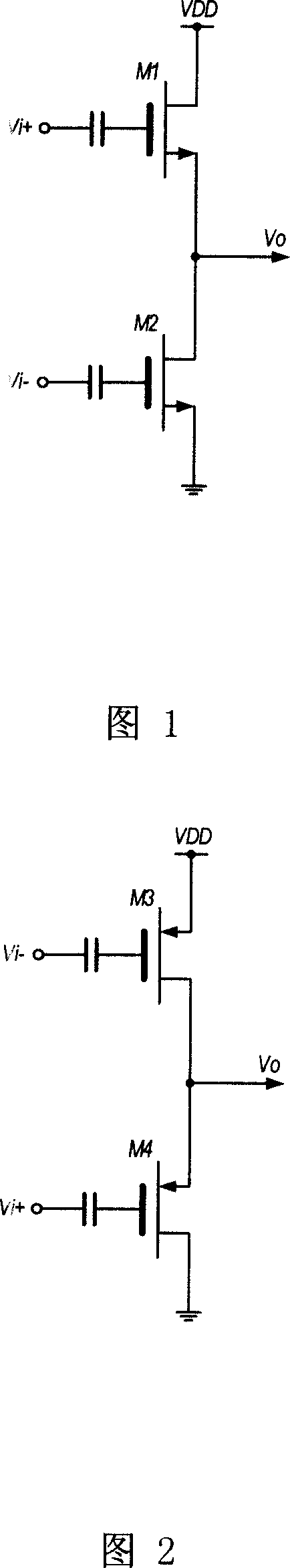
[0022] Referring to Fig. 1, the N-type radio frequency difference of the present invention comprises two N-type transistors M1 and M2 to the single-ended converter, the source of transistor M1 is interconnected with the drain of transistor M2 as output terminal Vo, and the drain of transistor M1 is connected to Power supply, the source ground wire of transistor M2, the positive terminal Vi+ of the differential input signal is input to the gate of transistor M1 through AC coupling (the DC bias circuit is omitted in the figure), and the negative terminal Vi- of the differential input signal is input to the transistor through AC coupling Gate of M2.

[0023] The transistor M1 constitutes a source follower, and the output terminal Vo follows the input Vi+ in the same direction. Transistor M2 constitutes a common-source amplifier, amplifying the input Vi- inversely. Since Vi+ and Vi- are reversed, the output of the source follower and the common source amplifier are in the same di...


PUM


Abstract

The present invention discloses a radio frequency differential-to-single-ended converter, the basic forms of the converter is separated to two types of N type and P type which are respectively realized with N-type transistor and P-type transistor. The N-type converter combines with the P-type converter and forms a push-pull type radio frequency differential-to-single-ended converter; wherein, the outputs of N-type converter and the P-type converter are respectively coupled to the output end Vo by the intercourse of the capacitances of C1 and C2; the input end is shared, namely a transistor M1 of the N-type converter and a transistor M4 of the P-type converter use one input end Vi+, a transistor M2 of the N-type converter and a transistor M3 of the P-type converter use one input end Vi-; and the push-pull type radio frequency differential-to-single-ended converter is formed. The invention has the advantages of wide scope of working frequency, providing additional gain, high efficiency, proportional load at two differential circuits, good linearity and easily integrating on the chip.

Description

technical field [0001] The invention relates to a radio frequency circuit, in particular to a radio frequency differential-to-single-end converter. Background technique [0002] The last stage of the transmitter is generally a power amplifier, which outputs a certain amount of power to the antenna, and then transmits it into space. At present, most mainstream power amplifiers adopt single-ended input form, while the circuit before the power amplifier usually adopts differential form to improve the ability to suppress noise. Therefore, a differential-to-single-ended converter needs to be inserted before the power amplifier. [0003] There are two main differential-to-single-ended conversion methods in use today: [0004] One is to use a balun (balun) to combine the differential signals into single-ended. Its disadvantages are: the difference loss is large, the realized circuit occupies a large area, and it is not easy to integrate on the chip. [0005] Another method is t...

Claims


Application Information

Patent Timeline
Patent Type & Authority Applications(China)
IPC IPC(8): H03F3/20H03F3/24H03F3/26H03F1/02H03F1/26H03F1/32H04B1/04
Inventor 魏述然胡海星
Owner RDA TECH
Why Eureka
Try Eureka