Exhaust valve assembly for a large two-stroke diesel engine

A diesel engine, stroke technology, applied in combustion engines, mechanical equipment, engine components, etc., can solve problems such as waste, and achieve the effect of simplified complexity and low construction height

Inactive Publication Date: 2008-04-09
MAN B & W DIESEL AS
View PDF4 Cites 13 Cited by
  • Summary
  • Abstract
  • Description
  • Claims
  • Application Information

AI Technical Summary

Problems solved by technology

The stored energy is not reused in the closing stroke, unlike a camshaft driven engine, it is wasted because there is no way to reuse it

Method used


Image

  • Exhaust valve assembly for a large two-stroke diesel engine
  • Exhaust valve assembly for a large two-stroke diesel engine
  • Exhaust valve assembly for a large two-stroke diesel engine

Examples


Embodiment Construction

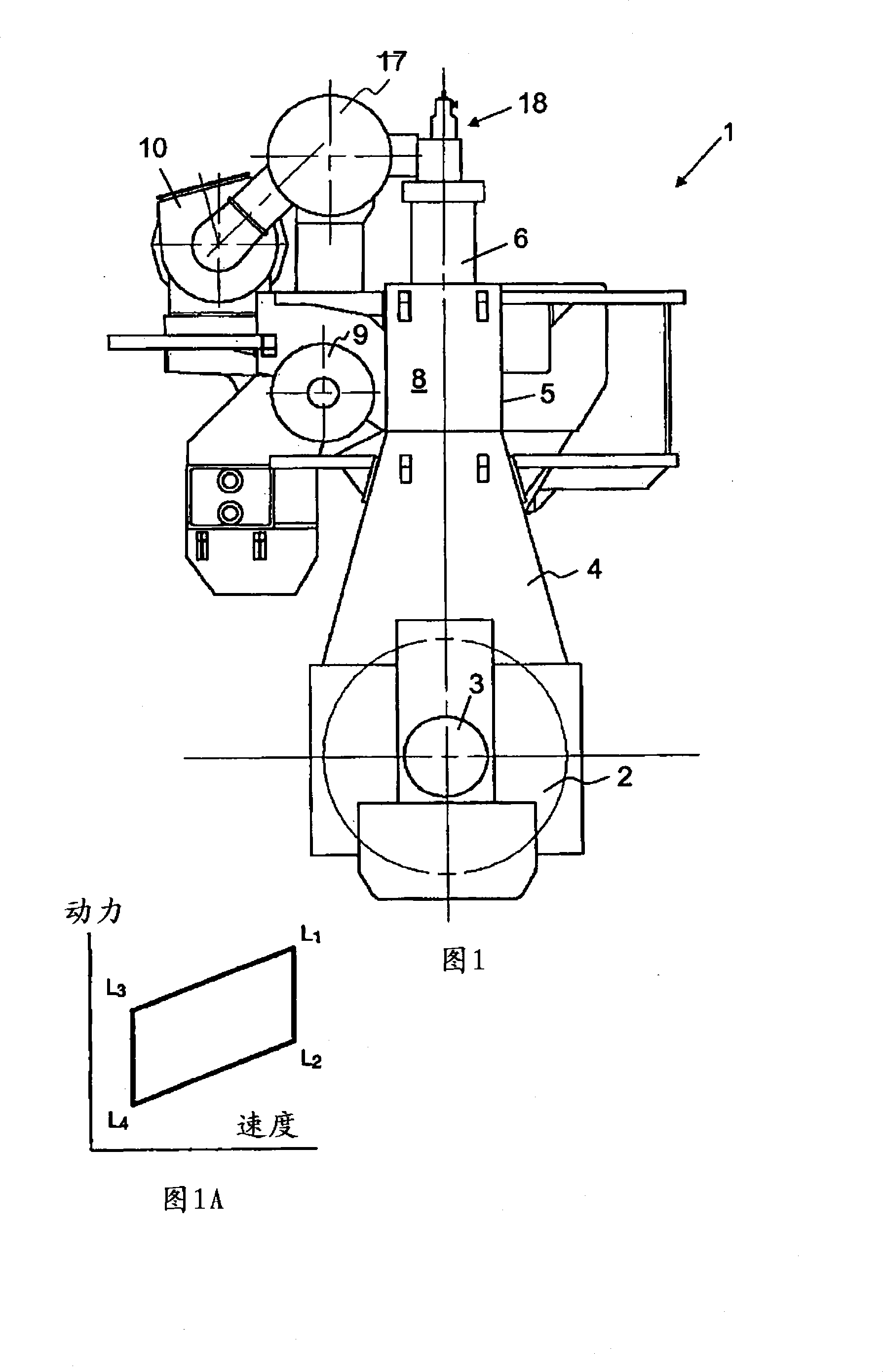
[0065] Figure 1 shows an engine 1 according to the invention. The engine is a low speed two stroke crosshead type diesel engine which may be a propulsion engine on a ship or a prime mover in a power plant. These engines typically have 6 to 12 in-line cylinders. The engine is built upwards from a base plate 2 with main bearings for the crankshaft 3 . The base plate is divided into sections of suitable size according to the available manufacturing equipment. An A-shaped crankcase frame 4 of welded design is mounted on the base plate. The cylinder block 5 is installed on top of the crankcase frame 4 . Tension bolts (not shown) connect the base plate to the cylinder block and hold the structure together. The cylinder 6 is supported by the cylinder block 5 . An exhaust valve assembly 18 is mounted on top of each cylinder 6 . The cylinder block 5 also carries an exhaust gas collector 17 , a turbocharger 10 and a scavenging gas collector 9 .

[0066] Figure 1A shows a layout f...


PUM


Abstract

The present invention relates to an exhaust valve assembly (18) for a large two-stroke diesel engine (1). The assembly (18) includes an exhaust valve (11) that is movable in opposite directions between a closed position and a open position. A double acting spring assembly (40) is operably connected to the exhaust valve (11) and forms a mass-spring system together with the exhaust valve (11) and the mass of any other parts moving in unison with the exhaust valve (11). The double acting spring assembly (40) stores energy during translation of the exhaust valve (11) back and forth between the closed and open position for subsequent propulsion of the exhaust valve (11) in an opposite direction. Hydraulic means (50) hold the exhaust valve (11) on command from a controller (27) in the closed or in the open position.

Description

technical field [0001] The present invention relates to large two-stroke diesel engines of the crosshead type, and in particular to large two-stroke diesel engines having a valve assembly comprising fluid-operated and electronically controlled actuators. Background technique [0002] Recently, crosshead-type large two-stroke engines generally used in propulsion systems of large ships or used as prime movers in power plants have been developed from camshaft-controlled engines to electronically-controlled engines. Electronic control provides improved flexibility for timing and shaping of fuel injection and exhaust valves. The combustion process can thus be better controlled, resulting in more efficient combustion and lower emission values, allowing smoke-free operation at all operating speeds, reducing part load fuel consumption and lowering minimum operating speeds. CN 1485530 (submitted to China), JP2004-084670 (submitted to Japan), KR 2004-20003 (submitted to Korea) disclo...

Claims


Application Information

Patent Timeline
Patent Type & Authority Applications(China)
IPC IPC(8): F02B1/12F02B75/00F01L9/02F01L1/46F01L9/10
CPCF02F2007/0097F01L1/465F01L9/02F01L9/10
Inventor 埃里克·甘巴里尼
Owner MAN B & W DIESEL AS
Why Eureka
Try Eureka