Engine cylinder head structure

A cylinder and engine technology, which is applied in the field of cylinder end structure devices, can solve the problems such as the inability to fully ensure the operating oil pressure of the variable valve synchronizing mechanism, the layout design constraints, and the increase in the overall length of the engine, so as to reduce the number of parts and reduce the number of parts. The effect of number and flow adequacy

Inactive Publication Date: 2008-04-30
SUZUKI MOTOR CORP
View PDF2 Cites 2 Cited by
  • Summary
  • Abstract
  • Description
  • Claims
  • Application Information

AI Technical Summary

Problems solved by technology

[0007] However, with regard to the oil pipe structure of the conventional engine, in the patent document 1 mentioned above, since the oil pipe is provided on the lubricating oil pipe of the camshaft, it is necessary to increase the number of parts in order not to interfere with the camshaft and the cylinder end cover. Piping the oil pipes will restrict the layout design and cause inconvenience
[0008] In addition, in Patent Document 2 mentioned above, the end journal of the camshaft becomes longer, which is inconvenient due to the increase in the overall length of the engine. In addition, when the end journal is shortened, it is not possible to ensure sufficient Inconvenience caused by running oil pressure

Method used


Image

  • Engine cylinder head structure
  • Engine cylinder head structure
  • Engine cylinder head structure

Examples


Embodiment 1

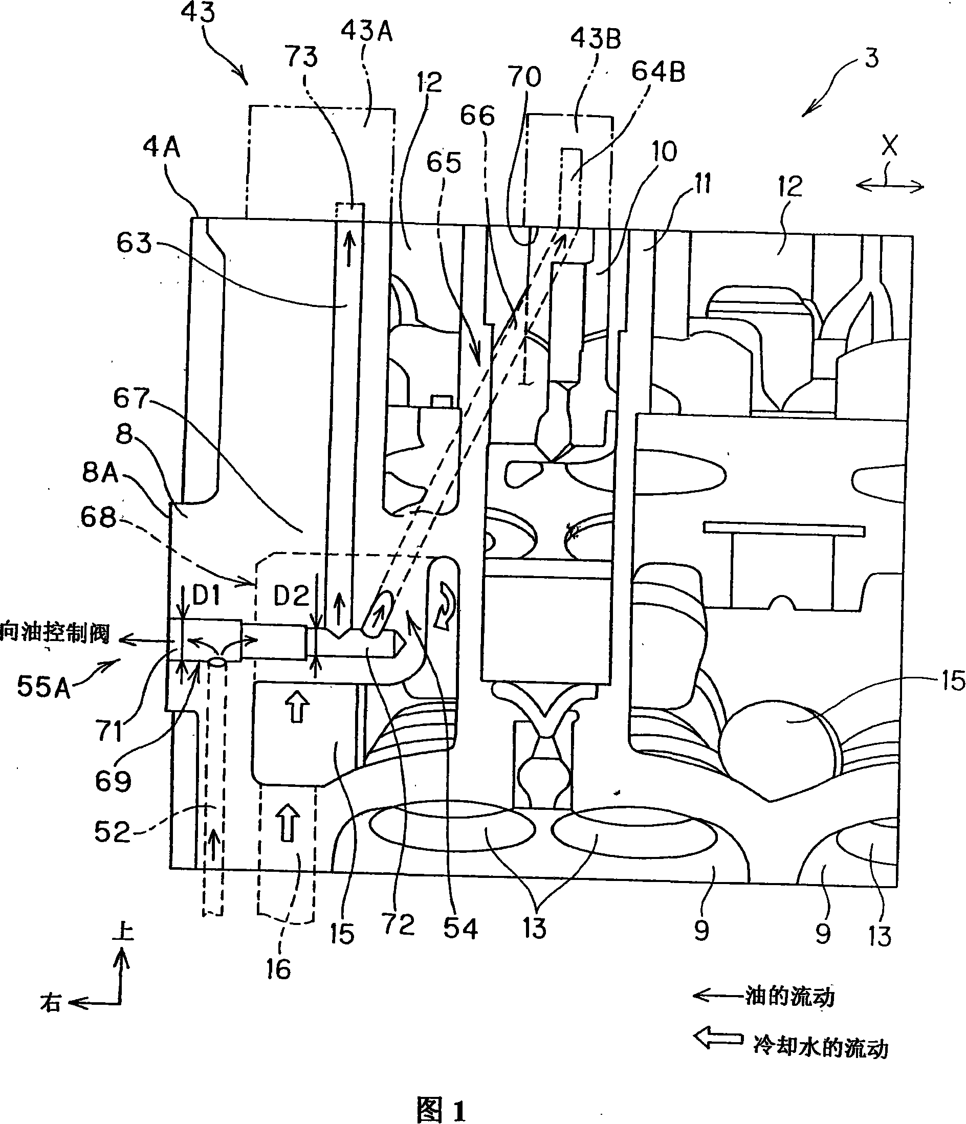
[0027] 1 to 7 show a first embodiment of the present invention. In Fig. 6 and Fig. 7, 1 is a vehicle-mounted multi-cylinder engine. The structure of this engine 1 is such that it is installed horizontally, and includes a cylinder block 2, a cylinder end 3, a cylinder end cover 4, and an oil pan 5, and is installed across the right sides of the cylinder block 2 and the cylinder end 3 to form a chain chamber. 6 for sprocket case 7. As shown in FIG. 1 , this sprocket case 7 is connected and mounted to the connection surface 8A of the end wall 8 of the cylinder end 3 .

[0028] As shown in Figure 1, on the cylinder end 3, corresponding to each cylinder, while the combustion chamber 9 is formed in the lower part, the spark plug hole wall 11 forming the spark plug hole 10 is formed in the upper part and the dynamic cylinder is formed around the spark plug hole wall 11. Valve chamber 12.

[0029] In addition, as shown in FIG. 5 , on the cylinder end 3 , corresponding to each cylin...

Embodiment 2

[0088] Fig. 8 shows a second embodiment of the present invention.

[0089] In the second embodiment, parts having the same functions as those in the above-mentioned first embodiment are denoted by the same symbols.

[0090] The features of the second embodiment are as follows. That is, on the end wall 8 of the cylinder end 3, while forming the branch oil pipe 81 communicating with the head side oil pipe 52 and guiding the oil to the oil control valve 49 side, a cam is formed on this branch oil pipe 81. The bearing oil groove 82 is further formed with a cam bearing oil pipe 83 communicating with the cam bearing oil groove 82 . The cam bearing groove 82 has a predetermined pipe area with a pipe width W, and functions as a regulating valve that restricts the amount of oil required for lubricating the camshaft. In addition, the cam bearing oil pipe 83 is formed inside the water jacket 15 of the cylinder head 3 .

[0091] In addition, on the end wall 8 of the cylinder end 3, a v...


PUM


Abstract

In a cylinder head structure of an engine, a structure of an oil passage is simplified to downside the engine and to provide proper flow of cooling water in the cylinder head. A partition wall is disposed in the cylinder head to separate an upward valve operating chamber from a downward water jacket. A boss section is formed at a position lower than the partition wall in an edge wall of the cylinder head, and has one end joined to a chain case and the other end protruding into the water jacket. A branch oil passage is formed in the boss section. The branch oil passage has a valve upstream-side passage section specified by a section toward the chain case with respect to a junction with a cylinder head-side oil passage. The linear communication passage section communicates between an end portion of the branch oil passage protruding into the water jacket and a camshaft cap coupling surface of a second camshaft bearing section.

Description

technical field [0001] The present invention relates to a cylinder end structure device of an engine, in particular to a cylinder end structure of an engine equipped with a variable valve synchronization mechanism. Background technique [0002] For a hydraulically driven engine with a variable valve synchronization mechanism, a transmission device is provided at the end of the camshaft, and there is a running oil pipeline that guides the oil from the oil pump to the transmission device, that is, the oil pipeline for the transmission device and the lubrication of the guide camshaft. The oil pipeline is the oil pipeline for the cam bearing. [0003] In the past, on the oil pipeline of the engine, the operating oil pipeline of the transmission device of the variable valve synchronous mechanism is connected with the terminal journal of the shaft end of the camshaft at the end of the cylinder, and the lubricating oil of the camshaft is set. In the case of oil pipes where the pip...

Claims


Application Information

Patent Timeline
Patent Type & Authority Applications(China)
IPC IPC(8): F01M1/06
CPCF02F1/40
Inventor 山田真嗣
Owner SUZUKI MOTOR CORP
Why Eureka
Try Eureka