Fiber discharging device suitable for automatic optical fiber winding machine

An optical fiber winding machine and automatic technology, applied in the coupling of optical waveguide, Sagnac effect gyroscope, etc., can solve the problems of unguaranteed winding quality, unstable transmission control, low precision of fiber arrangement, etc., and achieve excellent Transmission and control characteristics, stable fiber arrangement process, and the effect of reducing the natural frequency

Inactive Publication Date: 2008-04-30
BEIHANG UNIV
View PDF0 Cites 9 Cited by
  • Summary
  • Abstract
  • Description
  • Claims
  • Application Information

AI Technical Summary

Problems solved by technology

How to wind a high-quality fiber optic ring is very important to the development of fiber optic gyroscopes. There are many winding methods, and the quadrupole symmetrical winding method has the best effect, which is a method commonly used in the world. Manual winding is adopted, and there is no special

Method used


Image

  • Fiber discharging device suitable for automatic optical fiber winding machine
  • Fiber discharging device suitable for automatic optical fiber winding machine
  • Fiber discharging device suitable for automatic optical fiber winding machine

Examples


Embodiment Construction

[0039] The present invention will be further described in detail below in conjunction with the accompanying drawings.

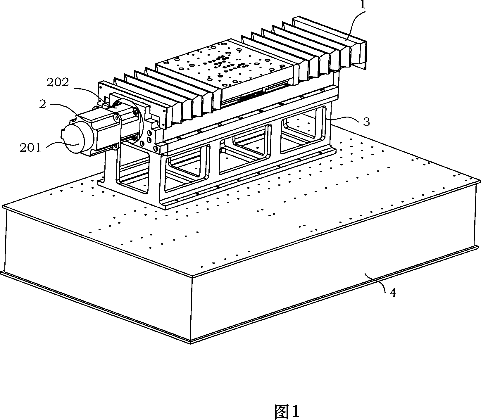
[0040] Please refer to Fig. 1 and Fig. 2, the present invention is a fiber-discharging mechanism applicable to an automatic optical fiber looping machine, the fiber-discharging mechanism is composed of a fiber-discharging assembly 1, a drive assembly 2 and a platform support 3; the platform support 3 The lower mounting surface 302 is fixedly installed on the precision platform 4, and the upper mounting surface 301 of the platform bracket 3 is fixed to the slide table base 13 of the fiber arrangement assembly 1; On the outer side, the motor 201 drives the workbench 12 to move back and forth on the slide base 13 to ensure the precise winding of the optical fiber on the fiber pay-off ring, guide wheel and fiber take-up ring.

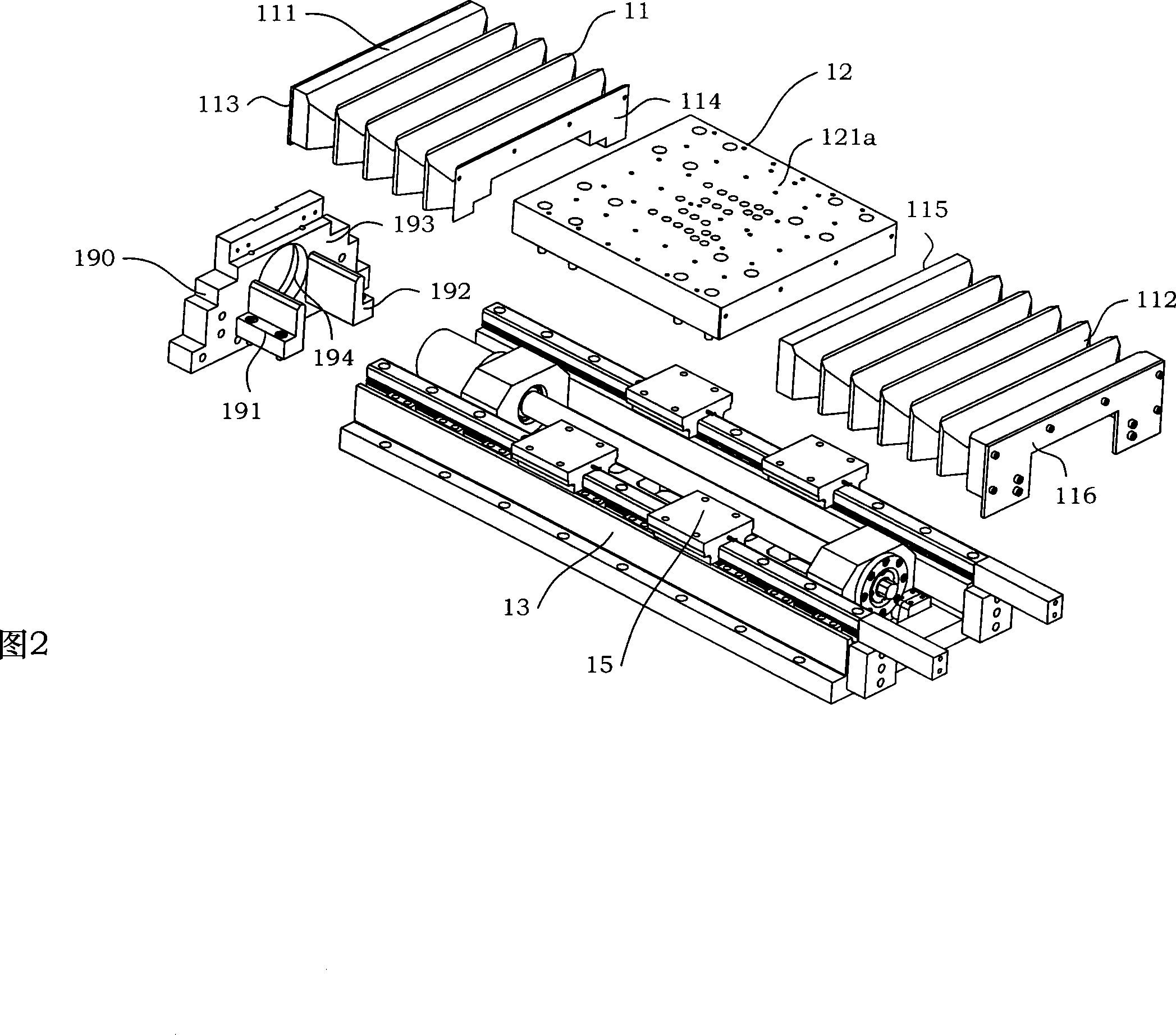
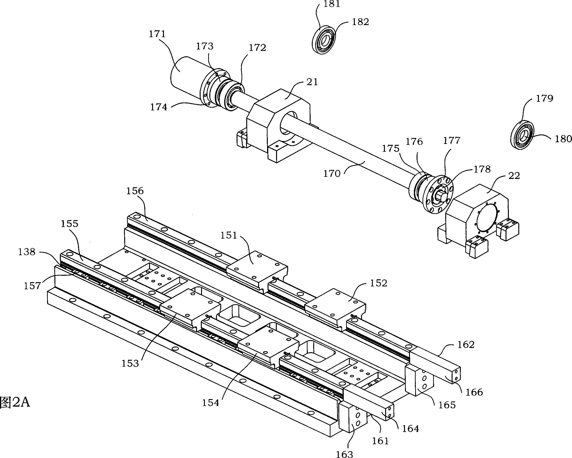
[0041] Please refer to FIG. 2 and FIG. 2A to FIG. 2F , the fiber arrangement assembly 1 in the present invention has the function of prec...


PUM


Abstract

The invention relates to a fiber arranging mechanism which is applied to an automatic optical fiber ring coiling machine, and the fiber arranging mechanism is composed of a fiber arranging component (1), a driving component (2) and a platform bracket (3). The lower installing face (302) of the platform bracket (3) is fixedly arranged on a precision platform (4). The upper installing face (301) of the platform bracket (3) is fixed with the slipway base (13) of the fiber arranging component (1). The fiber arranging component (1) is composed of an outer cover (11), a working table (12), the slipway base (13) and a sliding component (15). The fiber arranging mechanism of the invention is applied to the realization of fiber arranging function on various automatic optical fiber ring coiling machines, simultaneously, the invention also can be used in the machines such as optical fiber repeat coiling typed machines and optical fiber selecting machines. A screw lever (170) is driven to rotate by a motor (201), and the working table (12) can be made smoothly to slide on an A guiding rail (155) and a B guiding rail (156). Slight optical fibers can be accurately arranged on a preconcerted light fiber ring through adopting a frame with high stiffness, a prestressed assembling structure and an excellent driving and controlling characteristic in the fiber arranging mechanism.

Description

technical field [0001] The invention relates to a fiber-discharging mechanism, more specifically, to a fiber-discharging mechanism suitable for an automatic optical fiber looping machine. Background technique [0002] The fiber optic gyroscope was born in 1976. It is a new type of sensor that uses fiber optic sensing technology to measure the space inertial rotation rate. It has developed into a new mainstream instrument with epoch-making characteristics in the field of inertial technology. Compared with the laser gyroscope, it has higher precision, low cost, small size and light weight. The application prospect of fiber optic gyroscope is very broad. It is not only used in the navigation of aircraft and ships, missile guidance, high-precision position control of spacecraft, but also in the guidance of high-end cars in civilian use, as well as robots and automatic control systems, etc. . [0003] The fiber optic ring is the sensing core of the fiber optic gyroscope, and it...

Claims


Application Information

Patent Timeline
IPC IPC(8): G02B6/36G02B6/38G01C19/72
Inventor 张春熹董全林徐宏杰李立京伊小素
Owner BEIHANG UNIV
Why Eureka
Try Eureka