A converter for energy conversion of superconductive energy storage system

A superconducting energy storage and energy conversion technology, applied in the field of converters, can solve the problems of restricting the application of superconducting energy storage systems, unfavorable superconducting magnet system stability, increasing magnet AC loss, etc., achieving compact structure and reducing construction costs. Cost, effect of simplifying structural design

Inactive Publication Date: 2008-04-30
INST OF ELECTRICAL ENG CHINESE ACAD OF SCI
View PDF1 Cites 23 Cited by
  • Summary
  • Abstract
  • Description
  • Claims
  • Application Information

AI Technical Summary

Problems solved by technology

When the switch 20 is turned off, the voltage across the magnet is equal to the output voltage, and the superconducting magnet system is limited by low-temperature insulation and other conditions, and the voltage across the magnet cannot be very high, which makes the superconducting variable current with the above structure The device cannot be directly applied to the high-voltage system, which limits the application of the superconducting energy storage system. At the same time, when the output voltage is high, this method of directly cutting the magnet current will bring a lot of switching loss and increase The AC loss of the magnet is increased, which is not conducive to the stability of the superconducting magnet system

Method used


Image

  • A converter for energy conversion of superconductive energy storage system
  • A converter for energy conversion of superconductive energy storage system

Examples


Embodiment Construction

[0014] The present invention will be further described below with reference to the accompanying drawings and specific embodiments.

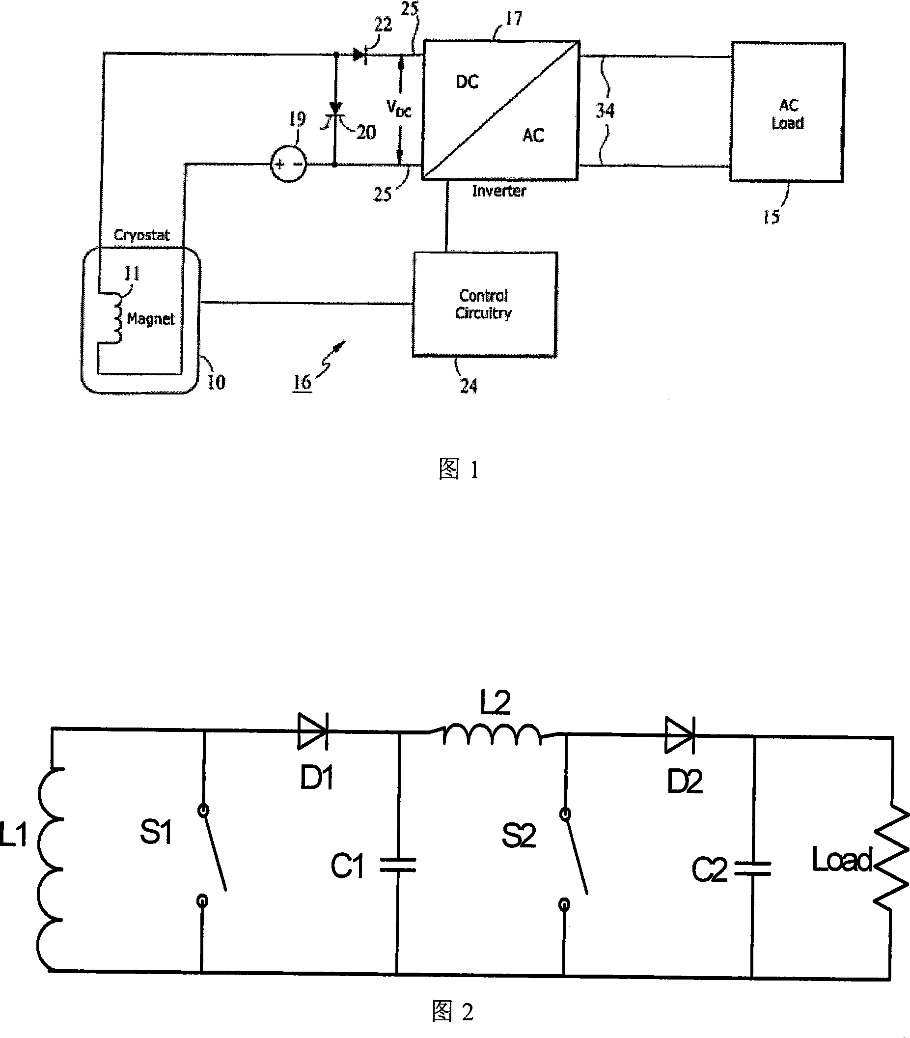
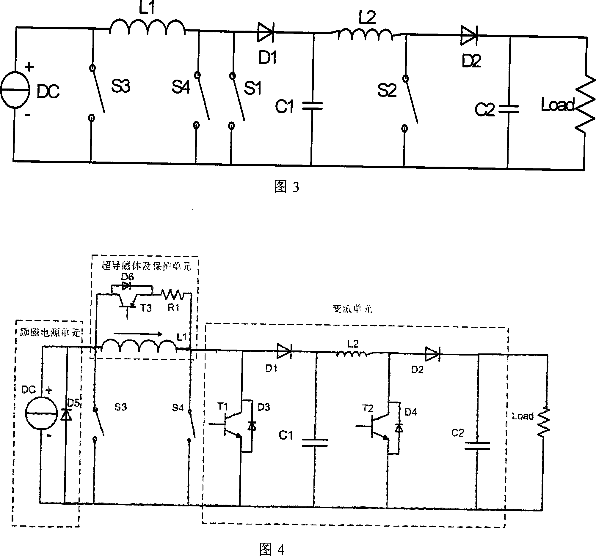
[0015] FIG. 2 is a schematic diagram of the main circuit of the present invention. As shown in Figure 2, L1 is a superconducting magnet, L2 is a continuous energy inductor, S1 is a first-stage chopper switch, D1 is a first-stage chopper diode, and C1 is a first-stage chopper capacitor. The anode of the diode D1 is connected in parallel with the superconducting magnet L1 and one end of the first-stage chopper switch S1 respectively, and the cathode of the diode D1 is connected in parallel with the first-stage chopper capacitor C1 and one end of the continuous energy inductor L2 respectively. The other end of the first-stage chopper capacitor C1 is connected in parallel with the superconducting magnet L1 and the other end of the first-stage chopper switch S1 respectively. When the switch S1 is closed, the current in the superconducting magnet L1 f...


PUM

PropertyMeasurementUnit
capacitanceaaaaaaaaaa

Abstract

A current transformer for energy conversion in a super-conductive energy storage system utilizes a two-stage boost-chopper to fulfill boost control for discharge process in super-conductive energy storage magnets. The first stage of the chopper circuit adopts a plurality of metal oxide semi-conductor field-effect transistors in parallel connection, so that the voltage on both ends of a super-conductive magnet can be limited in a rather low voltage level to meet the insulation requirements of the super-conductive magnet. The second stage of the chopper circuit increases the voltage to a higher level, and utilizes IGBTs as switch components to regulate subsequent output voltage through adjusting the switch duty cycle of the IGBTs through a PWM control mode, so as to fulfill the adjustable target for subsequent output voltage and the controllable target of the super-conductive magnet discharge voltage. The invention can realize energy output in the super-conductive energy storage magnet in a constant-voltage and DC mode, in order to meet the requirements for subsequent voltage-type loads. Meanwhile, the output voltage of the current transformer is not limited by insulating strength of magnets, but can fulfill flexible regulation according to subsequent load, and meanwhile, avoid the large volume problems with transformers or the multiple circuit topology structure.

Description

technical field [0001] The invention relates to a converter for charging and discharging a superconducting energy storage system. Background technique [0002] In recent years, with the development of power electronics technology, superconducting magnet technology and low temperature technology, with the improvement of the cost performance of superconducting materials, the ability of superconducting wires to carry current in strong magnetic fields has been greatly improved, and superconducting energy storage technology has become increasingly mature. received extensive attention. Superconducting magnets have replaced almost all bulky and power-hungry conventional magnets in high-energy physics experiments. In the field of superconducting power, micro-superconducting magnet energy storage systems have been commercialized abroad, and are widely used to improve power quality and power system stability. [0003] Superconducting magnet energy storage systems (SMES) have the adv...

Claims


Application Information

Patent Timeline
Patent Type & Authority Applications(China)
IPC IPC(8): H02J15/00H01F6/00
CPCY02E40/67Y02E40/60
Inventor 白烨单德鹏王秋良张文学
Owner INST OF ELECTRICAL ENG CHINESE ACAD OF SCI
Why Eureka
Try Eureka