
End-window X ray tube

A technology of X-ray tube and end window, which is applied in the directions of X-ray tube, X-ray tube electrode, X-ray tube parts, etc. Productization and mass production, reducing difficulty and manufacturing costs, and meeting the effect of mass production

Inactive Publication Date: 2008-05-07
BEIJING PURKINJE GENERAL INSTR
View PDF1 Cites 4 Cited by
  • Summary
  • Abstract
  • Description
  • Claims
  • Application Information

AI Technical Summary

Problems solved by technology

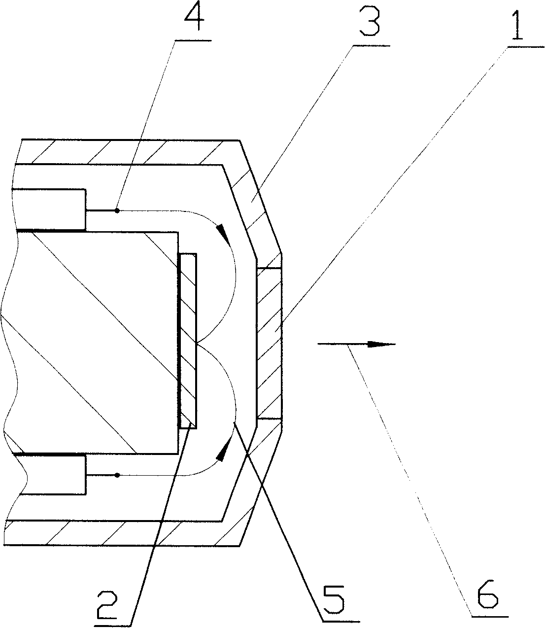
Its disadvantage is that the final incident direction of the electron beam bombarding the anode target surface is 180° from the outgoing X-ray direction, resulting in low intensity of bremsstrahlung.
[0004] 1. Due to the high voltage of the anode, the energy of the photoelectron beam generated is high, so it is not suitable for the measurement of light metals
Especially not applicable to the measurement of the five elements required by the RoHS Directive
[0005] 2. The structure is complex and the production process is strictly required
[0006] 3. The high voltage of the power supply increases the difficulty of power supply manufacturing, and at the same time increases the difficulty of insulation protection
Not suitable for the field of small portable instruments

Method used


Image

  • End-window X ray tube
  • End-window X ray tube

Examples


Embodiment Construction

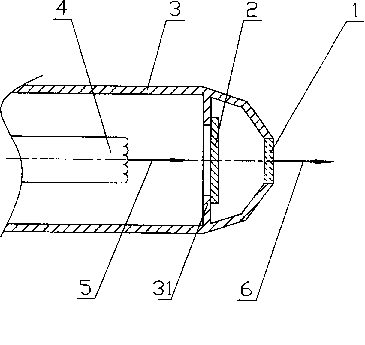
[0016] The end window X-ray tube described in this embodiment consists of figure 2 As shown, it includes a housing 3, a cathode filament 4 for emitting an electron beam 5, a thin film anode target 2, and a beryllium window 1. The shell 3 is made of copper-based material, and a ring-shaped bracket 31 for installing a thin film anode is installed inside the shell 3, and the shell 3 is directly grounded. The cathode filament 4 is encapsulated in the housing 3 and is powered by a voltage of -40kV. The beryllium window 1 is arranged on the end surface of the housing 3 and is located directly in front of the electron beam 5. The thin-film anode target 2 is arranged between the cathode filament 4 and the beryllium window 1. In this example, a thin-film molybdenum sheet with a thickness of 20 μm is used as the thin-film anode target 2. The thin-film anode target 2 is welded to the ring frame 31 inside the housing 3 , It can ensure good electrical and thermal contact. Because of the good t...


PUM


Abstract

The invention provides an end window X ray tube, which comprises a casing, a cathode filament used for transmitting electron beams, a thin film anode target and a berylium window. The cathode filament is encapsulated in the casing, the berylium window is arranged on the end face of the casing and positioned in front of the electron beam, the thin film anode target is arranged between the cathode filament and the berylium window, and the thin film anode target are fixedly connected inside the casing. Simultaneously, the invention adopts the earthing of casing and the negative high-voltage power supply mode of the cathode filament, and the casing which is electrically insulated and protected is avoided, thus being beneficial to the radiation of the X ray tube. The invention has the advantages that firstly, because X ray is required to penetrate through a thin film anode, and the X ray can emit from the end window, the low energy part of the X ray is filtered and weakened, the high energy part of the X ray is influenced little, thereby an X ray spectrum with weaker background is obtained; secondly, a more complex electric field is not required to control the deflection direction of an electron, thus being beneficial to the product-forming and the mass of the end window X ray tube.

Description

Technical field [0001] The invention relates to an end window X-ray tube, which belongs to an X fluorescence analysis instrument. Background technique [0002] X-ray tube is the core component of X-ray fluorescence analysis instrument, and its performance is directly related to the performance index of the instrument. The structure of a traditional end-window X-ray tube is shown in the figure below. The electron beam is emitted from the cathode, and the electric field strength is appropriately selected so that the electron beam is as follows under the action of the electric field force. figure 1 The trajectory shown bombards the target surface of the anode, generating X-rays. The disadvantage is that the final incident direction of the electron beam bombarding the anode target surface is 180° with the outgoing X-ray direction, resulting in low intensity of bremsstrahlung radiation. In addition, the existing structure needs to use an electric field to control the direction of mov...

Claims


Application Information

Patent Timeline
Patent Type & Authority Applications(China)
IPC IPC(8): H01J35/00H01J35/16H01J35/08
Inventor 田宇纮林德旭商颖健
Owner BEIJING PURKINJE GENERAL INSTR
Learn More