

High-speed curved printer capable of checking edition automatically
A curved printing machine, high-speed technology, applied in printing machines, rotary printing machines, general parts of printing machinery, etc., can solve the problem of inability to realize automatic color registration and other problems, and achieve the effect of scientific structure design
- Summary
- Abstract
- Description
- Claims
- Application Information
AI Technical Summary
Problems solved by technology
Method used
Image

Examples
Embodiment Construction
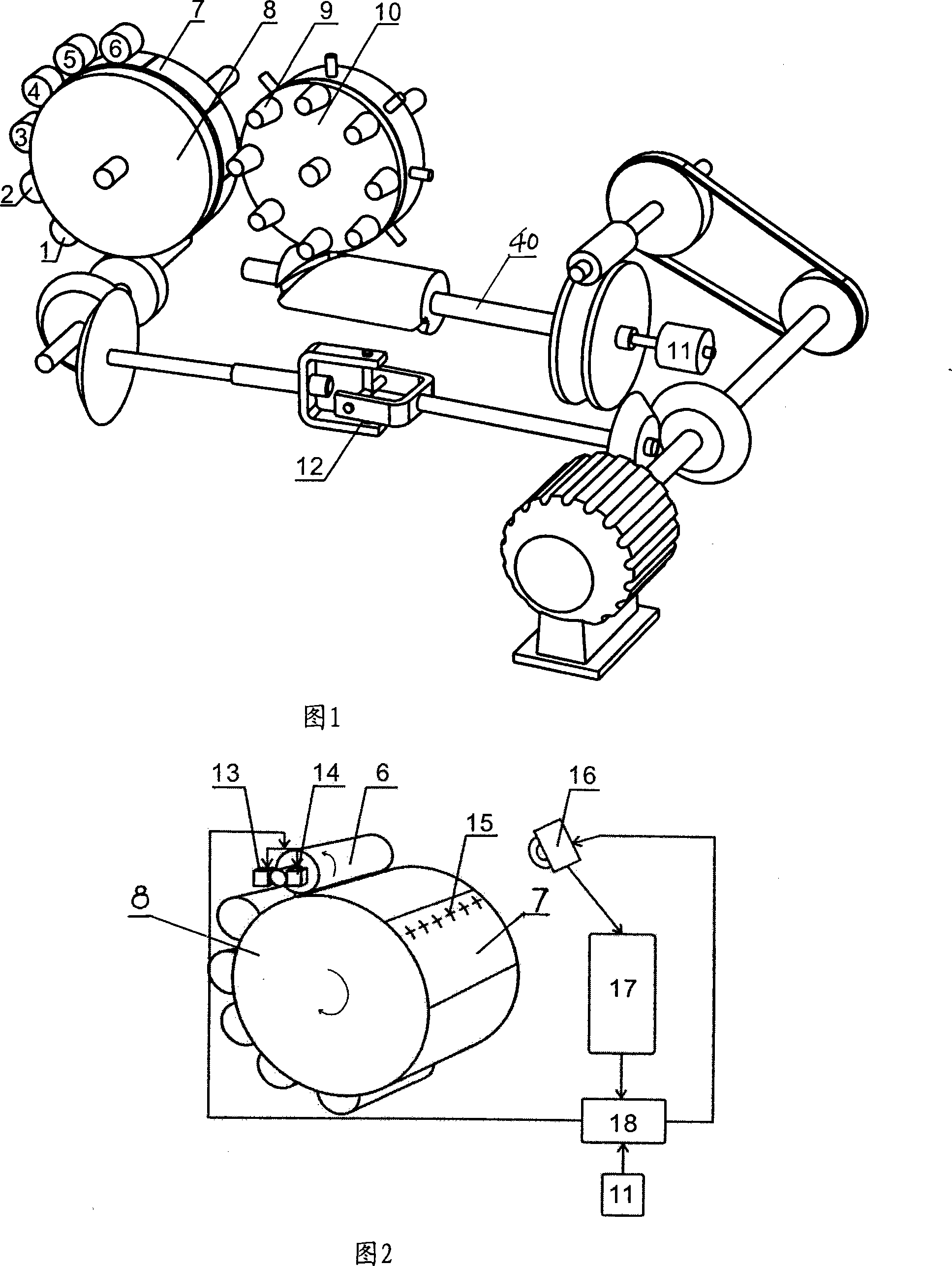
[0013] Figure 1 shows the structural schematic diagram of the entire curved surface printing machine. The entire curved surface printing machine is driven by a motor. When the motor is started, part of the movement of the motor drive shaft is transmitted to the large rubber roller through the drive shaft with universal coupling 12 8. The other part is transmitted to the material tray 10 through the pulley and the camshaft 40, and the motor transmission shaft, the transmission shaft with the universal joint 12 and the camshaft 40 rotate synchronously (that is, the transmission ratio between them is 1), The motor transmission shaft, the transmission shaft with the universal joint 12 and the camshaft 40 are collectively referred to as the main transmission shaft system, and the transmission ratio of the main transmission shaft to the large rubber roller and the material tray is 8:2:1.
[0014] A high-speed curved surface printing machine capable of automatic plate alignment, inclu...
PUM
 Abstract
Description
Claims
Application Information