
Method for accurately measuring micro-force and measuring micro-cantilever force constant

A precise measurement, micro-cantilever technique for applications such as force metering by measuring the frequency change of a stressed vibrating element

Inactive Publication Date: 2008-05-21
PEKING UNIV
View PDF0 Cites 11 Cited by
  • Summary
  • Abstract
  • Description
  • Claims
  • Application Information

AI Technical Summary

Problems solved by technology

Some companies (such as Nanofactory, Kleindiek) have developed systems for in-situ measurement of tiny forces. The principle of force measurement is also to use the micro-cantilever as a force sensor and measure the deflection of the cantilever with the help of piezoresistive properties, but what they can currently obtain The accuracy is only on the order of 10nN (nano Newton)

Method used


Image

  • Method for accurately measuring micro-force and measuring micro-cantilever force constant
  • Method for accurately measuring micro-force and measuring micro-cantilever force constant
  • Method for accurately measuring micro-force and measuring micro-cantilever force constant

Examples


Embodiment 1

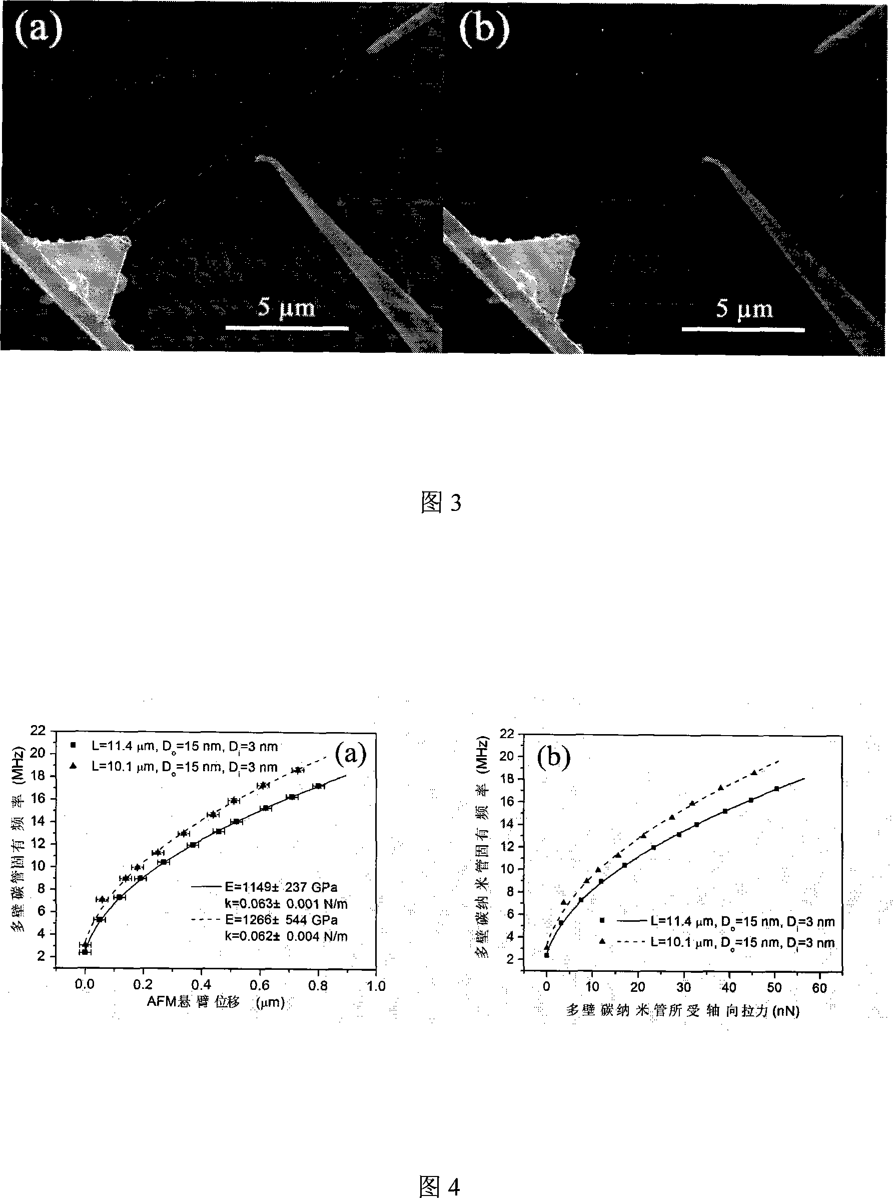
[0058] Embodiment 1: Using multi-walled carbon nanotubes to measure the tiny deflection force when the AFM cantilever is deflected, and the force constant of the AFM cantilever, the specific steps are as follows:

[0059] (1) Multi-walled carbon nanotubes were prepared by arc discharge method.

[0060] (2) Corroding a tungsten wire with a diameter of 0.2-1 mm with NaOH solution to obtain a needle tip with a radius of curvature less than 100 nm, and installing the needle tip in the needle tip casing of the nanoprobe.

[0061] (3) Coat the surface of the silicon carbide AFM cantilever with 50nm thick Au, and glue the Au-plated silicon nitride AFM cantilever to one end of a tungsten wire with silver glue, and install the other end of the tungsten wire on the nanoprobe Needle tip in sleeve.

[0062] (4) Install two nanoprobe systems equipped with tungsten tips and an AFM cantilever in the scanning electron microscope. When installing, the axis of the pyramid-shaped tip on the AFM...

Embodiment 2

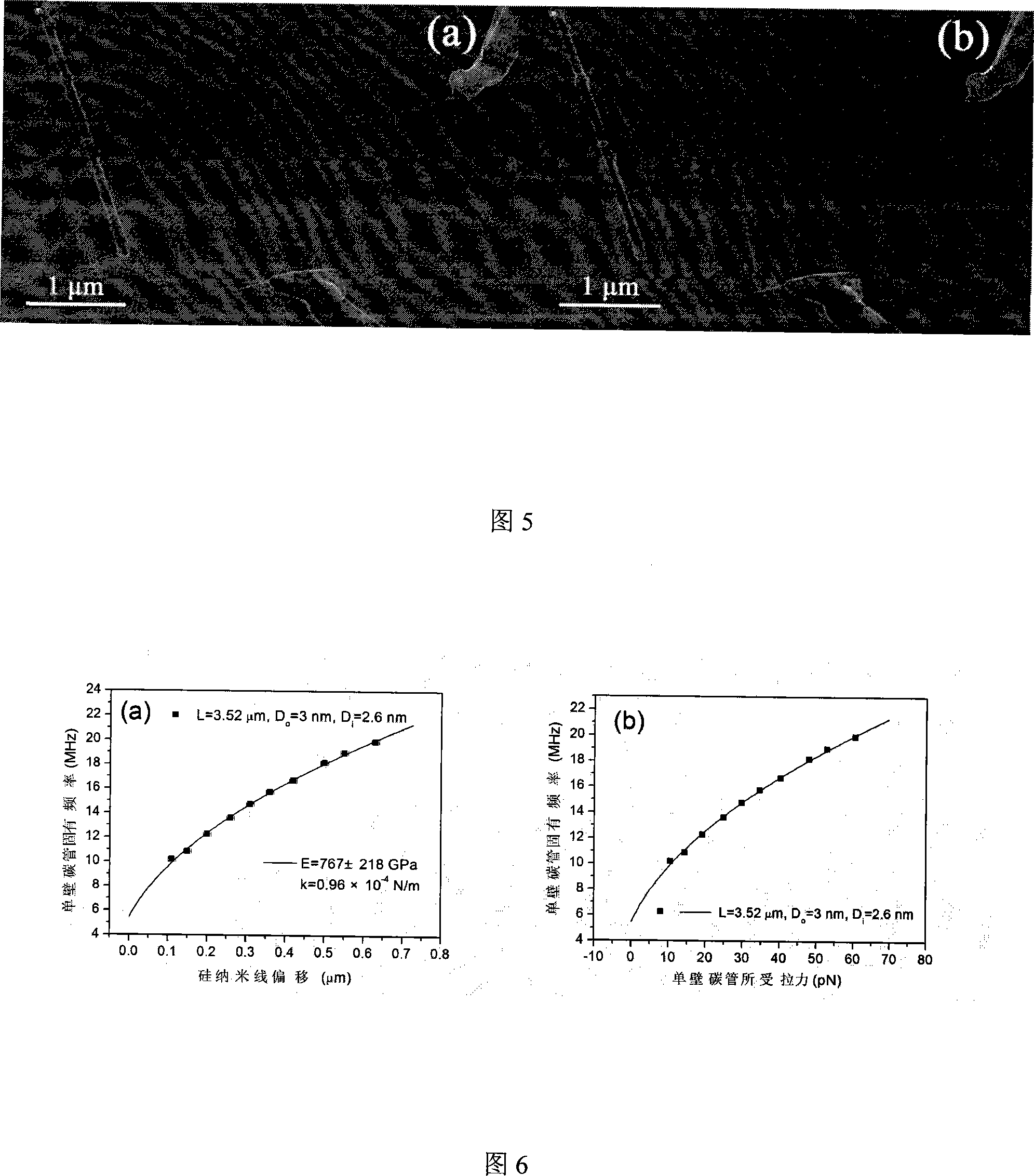
[0073] Example 2: Using single-walled carbon nanotubes to measure the tiny deflection force of metal-coated silicon nanowires during deflection, and the force constant of metal-coated silicon nanowires

[0074] The implementation steps are basically the same as those in Example 1, except that the multi-walled carbon nanotubes in Example 1 are replaced by single-walled carbon nanotubes, and the AFM cantilever is replaced by metal-coated silicon nanowires. The scanning electron micrograph of single-walled carbon nanotubes in Figure 5 shows that the two ends of a single-walled carbon nanotube are respectively fixed on a metal-coated silicon nanowire and a tungsten tip, and are fixed on the other tungsten tip. The fundamental mode resonance occurs under the applied alternating electric field force (see Figure 5b). Figure 6a shows the experimentally measured f-d data (see data points) of a single-walled carbon nanotube with a length of 3.52 μm, an outer diameter of 3 nm, and an inn...


PUM

PropertyMeasurementUnit
lengthaaaaaaaaaa
force constantaaaaaaaaaa

Abstract

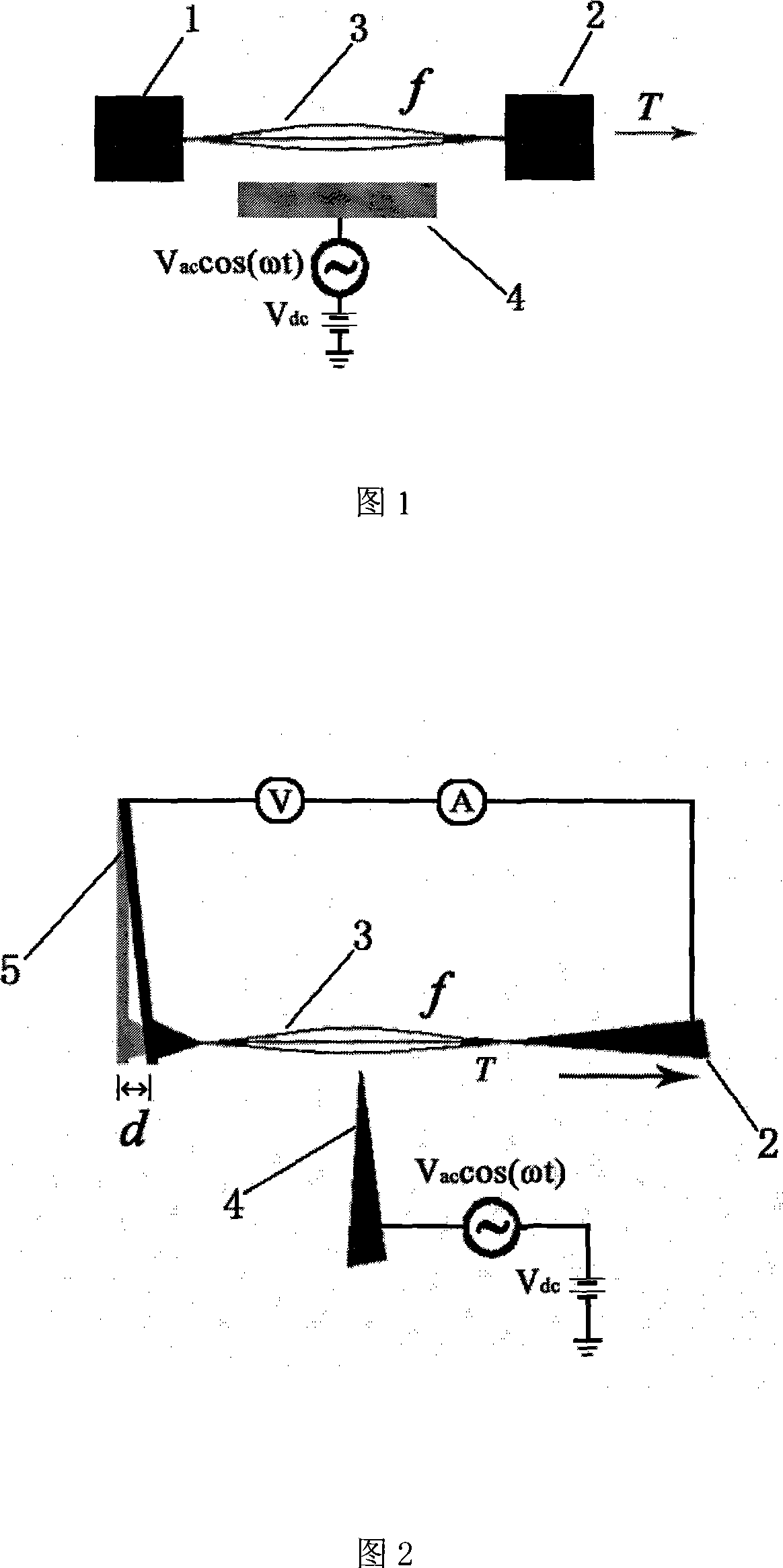
The invention provides a method for accurately measuring a tiny force and a force constant of a micro-cantilever, belonging to the field of nanometer measurement. In this method, the two ends of a nanomaterial are fixed on two fulcrums, and a small axial pulling force T is applied to the nanomaterial; on the side of the nanomaterial, an electrode is placed in the middle of the nanomaterial, and a The alternating voltage excites the nanomaterial to make it resonate, and the natural frequency f of the nanomaterial is measured; according to the material characteristics and geometric characteristics of the nanomaterial and the boundary conditions of the nanomaterial, the natural frequency of the nanomaterial is calculated from the vibration equation. The relationship between the axial tensile force received, that is, the f-T curve of the nanomaterial; according to the natural frequency f measured above, the magnitude of the micro tensile force T is obtained. The method is further used to measure the micro-deflection force of the micro-cantilever when it is deflected, and the force constant of the micro-cantilever is measured in combination with the measurement of the deflection displacement. The invention can be used to develop an instrument for accurately measuring tiny forces of the order of pico-newtons or even flying newtons.

Description

technical field [0001] The invention belongs to the field of nanometer measurement, in particular to a method for accurately measuring tiny force and the force constant of a microcantilever. Background technique [0002] Nanometrics is an important field of current nanotechnology research. The measurement of nano-Newton or even pico-Newton and femto-Newton force is necessary for the study of the mechanical properties of nanomaterials and the laws of mechanics at the nanoscale. [0003] At present, one of the technologies for measuring tiny forces is to use silicon resonators made by micromachining technology as force sensors. It has been reported that the force sensitivity of force sensors made of silicon resonators can reach 64KHz / N. However, since it is still difficult to make the silicon resonator to the nanometer scale in the micromachining process, it is difficult to further improve the force sensitivity of the silicon resonator. Nanomaterials grown by physical and c...

Claims


Application Information

Patent Timeline
Patent Type & Authority Applications(China)
IPC IPC(8): G01L1/10
Inventor 魏贤龙陈清彭练矛
Owner PEKING UNIV
Learn More