Organic electroluminescent LED manufacturing method and the buffering conversion cavity using the same

A manufacturing method and diode technology, applied in semiconductor/solid-state device manufacturing, circuits, electrical components, etc., can solve the problem that defects cannot be repaired online, and achieve the effect of reducing dependence and improving yield

Active Publication Date: 2008-05-21
TRULY SEMICON
View PDF0 Cites 6 Cited by
  • Summary
  • Abstract
  • Description
  • Claims
  • Application Information

AI Technical Summary

Problems solved by technology

The existing buffer cavity only serves to transfer the conversion environment, and cannot repair defects online

Method used


Image

  • Organic electroluminescent LED manufacturing method and the buffering conversion cavity using the same
  • Organic electroluminescent LED manufacturing method and the buffering conversion cavity using the same
  • Organic electroluminescent LED manufacturing method and the buffering conversion cavity using the same

Examples


Embodiment Construction

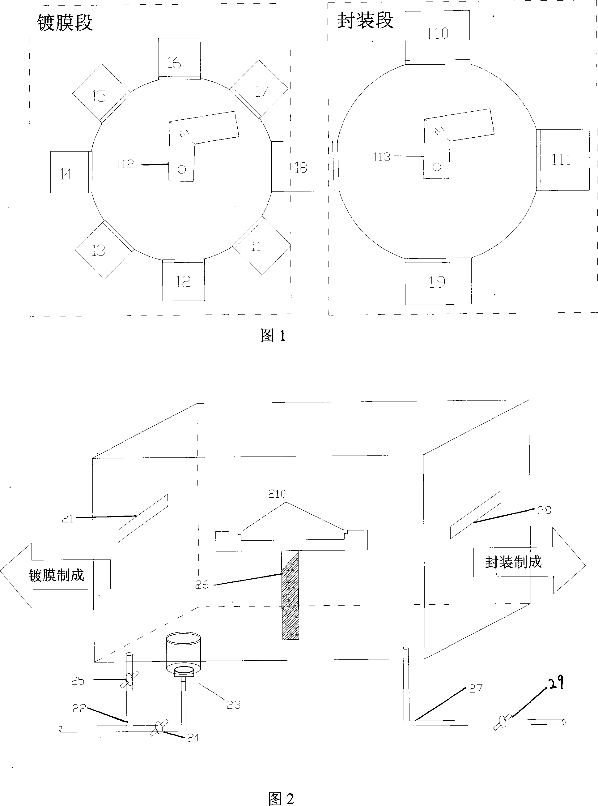
[0023] The OLED manufacturing process is shown in Figure 1. The substrate in the OLED device is used as the support of the organic electroluminescent device. Generally, a glass substrate or a plastic substrate is used. The glass substrate can be made of lime soda glass or borosilicate glass, and the plastic substrate can be polyester. or polyimide compounds. The anode is a transparent electrode, which is made on the substrate and can be made of inorganic materials or conductive polymer materials. The inorganic materials are generally indium tin oxide (ITO) or indium zinc oxide (IZO), or gold, copper, silver, etc. High-function metal.

[0024] The ITO is carved into strips for use as a light-emitting anode, and a layer of non-conductive organic resin material (commonly used PSPI) is formed on the substrate by spin coating in the ITO direction and perpendicular to the ITO direction. form the desired pattern. At the same time, a layer of negative organic resin material is made ...


PUM


Abstract

The invention discloses a manufacture method of organic electroluminescent LEDs, comprising a coating stage, an environment conversion-transmission stage in a cushioning-conversion cavity, an encapsulation stage on a high purity N2 environment and an electric and gaseous processing stage. The invention is characterized in that: each organic functional layer is deposited on a base plate on a high-vacuum environment at the coating stage, and the coated base plate is put up with the electric and gaseous processing via an outboard electrical source in the cushioning-conversion cavity; the device is put up with the electric and gaseous processing in a transmission-conversion cavity on a production line, and when the current is switched on, a bigger current flows through a short-circuit drawback of the device and the short-circuit drawback is burnt out; the short-circuit drawback can be oxidized by oxygen or other gas processing and then loses electrically conductive function. The invention has the advantage of easily taking out the local short-circuit drawback area.

Description

technical field [0001] The present invention relates to a manufacturing method of an organic electroluminescent diode, and the present invention also relates to a buffer conversion cavity used in the manufacturing method. Background technique [0002] An organic electroluminescent diode (OLED) is an organic electroluminescent device whose light-emitting mechanism is that holes and electrons are injected from the anode and cathode, respectively, and then pass through their respective transport layers to reach the light-emitting layer, where holes and electrons are located in the light-emitting layer. combine to emit photons. Depending on the energy level of the material, different colors of light can be emitted according to ΔE=hv. In the structure of OLED, except for the anode and cathode, the materials of the other components are almost all organic compound materials; due to the limitation of the transmission capacity of the semiconductor material itself, these structures c...

Claims


Application Information

Patent Timeline
Patent Type & Authority Applications(China)
IPC IPC(8): H01L51/56
Inventor 范家寿柯贤军
Owner TRULY SEMICON
Why Eureka
Try Eureka